


R
mPGA604 Socket Design Guidelines 13
3 Mechanical Requirements
3.1 Mechanical Supports
A retention system needs to isolate any load in excess of 50 lbf, compressive, from the socket during
the shock and vibration conditions outlined in Sections 5. The socket must pass the mechanical
shock and vibration requirements listed in Sections 5 with the associated heatsink and retention
mechanism attached. socket can only be attached by the 603 contacts to the motherboard. No
external (i.e. screw, extra solder, adhesive, etc.) methods to attach the socket are acceptable.
3.2 Materials
3.2.1 Socket Housing
Thermoplastic or equivalent, UL 94V-0 flame rating, temperature rating and design capable of
withstanding a temperature of 240°C for 40sec (minimum) typical of a reflow profile for solder
material used on the socket. The material must have a thermal coefficient of expansion in the XY
plane capable of passing reliability tests rated for an expected high operating temperature, mounted
on FR4-type motherboard material.
3.2.2 Color
The color of the socket can be optimized to provide the contrast needed for OEM’s pick and place
vision systems. The base and cover of the socket may be different colors as long as they meet the
above requirement.
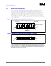
3.3 Cutouts for Package Removal
Recessed cutouts are required in the side of the socket to provide better access to the package
substrate, and facilitate the manual removal of inserted package. Figure A-6.
3.4 Socket Standoff Height
Socket stand off height, cover lead in and cover lead in depth must not interfere with package pin
shoulder at worst-case conditions. The processor (not the pin shoulder) must sit flush on the socket
standoffs and the pin field cannot contact the standoffs. Figure A-5.