


Electrical Requirements
R
26 mPGA604 Socket Design Guidelines
4. Calibration – Cascade Calibration Substrates or equivalent.
5. Measurement objects – packages, sockets, motherboards.
Measurement Steps:
• Equipment Setup
Cables should be connected to the network analyzer and to the probes using the
appropriate torque wrench to ensure consistent data collection every time the
measurement is performed.
• Set VNA
Bandwidth = 30 0KHz – 3 GHz with 801 points.
Averaging Factor = 16.
• Perform Open/Short/Load calibration:
Calibration should be performed at the start of any measurement session.
Create Calibration Kit if necessary for 1
st
time.
Do not perform port extension after calibration.
• Check to ensure calibration successfully performed.
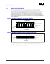
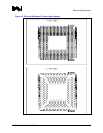
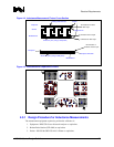
• Measure the inductance of configuration 4 of the package mounted on the socket, which is
mounted to the motherboard fixture (Figure 4-5):
Call this
assemblysocket
L .
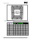
Export data into MDS/ADS or (capture data at frequency specified in Item 6 of
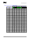
Table 4-1).
• Measure the inductance of configuration 4 of the package mounted on the socket, which is
mounted to the motherboard fixture (Figure 4-5). Call this
sandwich
L :
Measure 30 units.
The package for 30 units must be chosen from different lots. Use 5 different lots, 6 units
from each lot.
Export data into MDS/ADS or (capture data at frequency specified in Item 6 of
Table 4-1).
Calculate
sandwich
L .
For each socket unit, calculate
sandwich
assemblysocketsocket
LLL −=
It means
sandwich
L will be subtracted from each
assemblysocket
L and the result will be
compared with spec value for each individual socket unit.
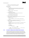
4.3.2 Correlation of Measurement and Model Data Inductance
To correlate the measurement and model data for loop inductance, one unit of measured socket
assembly (socket and shorted test fixture) and one unit of measured sandwich (shorted test fixture)
will be chosen for cross-sectioning. Both units will be modeled based on data from cross-sectioning
using Ansoft 3D*. The sandwich inductance will be subtracted from socket assembly inductance for
both measured and modeled data. This procedure results in loop inductance for socket pin +
interposer pin. This final result can be compared with the loop inductance from the supplier model