


Mechanical Requirements
R
16 mPGA604 Socket Design Guidelines
3.9.6 Lubricants
For the final assembled product, no lubricant is permitted on the socket contacts. If lubricants are
used elsewhere within the socket assembly, these lubricants must not be able to migrate to the
socket contacts.
3.10 Material and Recycling Requirements
Cadmium shall not be used in the painting or plating of the socket.
CFCs and HFCs shall not be used in manufacturing the socket. It is recommended that any plastic
component exceeding 25g must be recyclable as per the European Blue Angel recycling design
guidelines.
3.11 Lever Actuation Requirements
• Lever closed direction – right.
• Actuation direction called out in Figure A-5.
• 135° lever travel max.
• Pivot point in the center of the actuation area on the top of the socket. Figure A-6.
3.12 Socket Engagement/Disengagement Force
The force on the actuation lever arm must not exceed 44N to engage or disengage the package into
the mPGA604 socket. Movement of the cover is limited to the plane parallel to the motherboard.
The processor package must not be utilized in the actuation of the socket. Any actuation must meet
or exceed SEMI S8-95 Safety Guidelines for Ergonomics/Human Factors Engineering of
Semiconductor Manufacturing Equipment, example Table R2-7 (Maximum Grip Forces).
3.13 Visual Aids
The socket top will have markings identifying Pin 1. This marking will be represented by a clearly
visible triangular symbol. See Figure A-6.
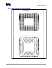
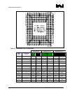
3.14 Socket BGA Co-Planarity
The co-planarity (profile) requirement for all solder balls on the underside of the socket is located in
Figure A-5.
3.15 Solder Ball True Position
The solder ball pattern has a true position requirement with respect to Datum A, B, and C (see
Figure A-5).