


Page 2-17
2-17
Microwave Oven Hood Combo Service Manual — LIT 4317216
Original 03/97
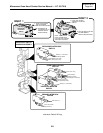
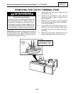
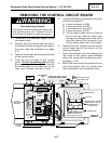
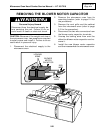
REMOVING THE CONTROL CIRCUIT BOARD
WARNING
Personal Injury Hazard
Disconnect from the electrical supply be-
fore servicing the unit. Failure to do so
could result in death or electrical shock.
1. Disconnect the electrical supply to the
microwave oven.
2. Remove the two screws from the top of
the cabinet for the vent grille and remove
the grille (see the illustration on page
2-3).
3. Remove the screw from the top center tab
of the control panel.
4. From the top and back of the control
panel,
lift the top locking tab and pull
the top of the panel out slightly, then lift
the bottom tabs of the panel out of the
slots, pull it forward, and turn it over.
1
2
CN1
CN2
RY2
CN4
14
1
CN3
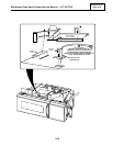
TURN BOARD OVER
CIRCUIT
BOARD
SCREW
(4)
TOP LOCKING
TAB
SLIDE
BOARD UNDER
BRACKET
CONTROL
CIRCUIT
BOARD
CONTROL
PANEL
BOTTOM
TABS
BOTTOM
SLOTS
TAB
SLOT
RIBBON
CABLE
TOP CENTER TAB
MOUNTING SCREW
SLOT
TAB
TECH SHEET
UNSNAP/SNAP LOCKING
ARMS ON COLLAR TO
BOTTOM SIDE OF
CONNECTOR
INSERT CABLE INTO
REAR CONTACT SLOT
RIBBON CABLE
COLLAR
CONNECTOR
CN3
INSET
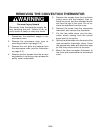
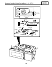
5. Unplug the following connectors from the
control circuit board:
a) 3-wire connector at CN4.
b) 2-wire connector at CN2.
c) 2 connectors on relay RY2.
d) 8-wire connector at CN1.
e) Lift the ribbon cable collar at CN3 as
far as it will go, (see the inset), then
unsnap the locking arms on the collar
from the sides of the connector, and
lift the ribbon cable out of the socket.
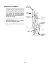
6. Remove the four screws from the control
circuit board and lift the board off the
mounting bracket.
7. Clean the surface of the new display and
the inside of the control panel window
with a soft, damp cloth to remove any dirt,
smudges, or lint.
8. Mount the new control circuit board to the
mounting bracket with four screws and
then reassemble the microwave oven.