


Page 3-25
3-25
Microwave Oven Hood Combo Service Manual — LIT 4317216
Original 03/97
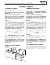
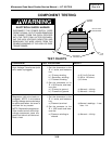
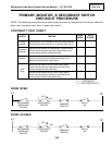
PRIMARY, MONITOR, & SECONDARY SWITCH
CHECKOUT PROCEDURE
L1
RELAY
#2
SECONDARY
INTERLOCK
SWITCH
OVEN LIGHTS
SWITCH
MONITOR
SWITCH
N.C.
N.O.
C
N
DOOR CLOSED
DOOR OPEN
L1
RELAY
#2
SECONDARY
INTERLOCK
SWITCH
OVEN LIGHTS
SWITCH
MONITOR
SWITCH
N.C.
N.O.
C
N
NOTE: The following chart and strip circuits show the continuity and position of the door switches
when the microwave oven door is open and closed.
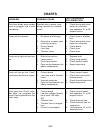
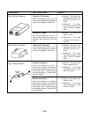
SWITCH TESTING
DOOR
OPEN
DOOR
CLOSED
Primary
Interlock
Disconnect the 4-pin connector from the control module.
Check from the pink wire (pin 1) to the blue wire (pin 3).
–+
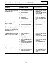
Secondary
Interlock
Disconnect the wires at the Secondary Interlock Switch.
Check from the common terminal (white wires) to the
normally-open terminal (red/white wires).
–+
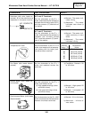
Monitor
Disconnect the wires from the Monitor Switch. Check
from the common terminal (red/brown wires) to the
normally-closed terminal (white wire).
+–
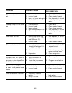
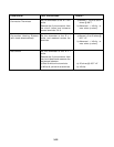
Oven
Lamp
Disconnect the wires from the Oven Lamp Switch.
Check from the common terminal (blue wire) to the
normally-closed terminal (red wire).
+_
Disconnect the wires from the Oven Lamp Switch.
Check from the common terminal (blue wire) to the
normally-open terminal (pink/black wire).
–+
(+) = CONTINUITY
(–) = NO CONTINUITY
CONTINUITY TEST CHART