


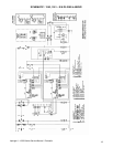

Impinger I -–1000 Series Service Manual - Domestic
23
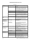
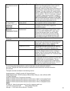
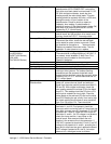
Pilot flame but no main
flame
Spark Ignitor (Flame Sensor) (There should be a visible pilot flame at this time).
NOTE: The Honeywell Ignition Control uses the
spark ignitor as the flame sensor. If spark
continues, check for proper ground connections at
Ignition Control. Check pilot orifice for any partial
blockage. If the above checks OK, replace ignition
control. If spark stops when pilot is lit, check for 24
VAC across M.V. - M.V/ P.V. terminals, if voltage is
not present, replace ignition control. If voltage is
present at terminals M.V. - M.V./P.V., the indicator
light on the control panel should be on, verify that
the main valve has opened, connect manometer to
manifold gas pressure tap(located on the
Temperature Control Valve
(Robert Shaw)
Check for gas supply at temperature control. Check
for temperature control set above 300°F.
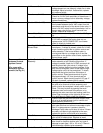
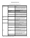
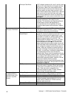
Red Indicator Light is
on, but no main
flame(For ovens with
mechanical
thermostat)
Main Orifice Check for blockage of main orifice. If there is no
blockage to the main orifice, replace the
temperature control.
(For ovens with
Electronic
Temperature Control)
Temperature Control
Potentiometer
Check for 120 VAC across L1 and L2on
temperature control board. Potentiometer (1000
ohm,1 turn) WITH POWER OFF: check ohms
across red and black leads, the ohm reading
should be 0 to1000 ohms as the dial is turned.
From green to red, the reading should be 1000
ohms steady throughout the full turn of the dial.
NOTE: Ovens S/N Q18037 and above, the potentiometer is internal to temperature control. Proceed to next
component.
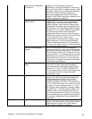
Thermocouple Probe Remove thermocouple leads from the temperature
control board, and measure the millivolt output of
these leads. Refer to chart on page 38 in the
adjustment section for proper readings.
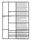
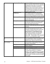
Temperature Control Turn temperature control dial to full "on" position.
Measure for 120 VAC across terminals "N.O." and
"L2", if voltage is not present; replace control.
Solenoid Valve If voltage is present at terminals "N.O."and "L2",
check for voltage at solenoid valve. If voltage is
present, listen for valve to open and close. Also,
check for opens and shorts in coil. If solenoid valve
is defective, replace
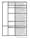
Intermittent Heating Both the main fan motor and burner blower motor
are equipped with thermo-protection and will cease
to operate when not cooled properly. This can
cause the units to cycle on and off intermittently.
Also, most of the problems listed under "oven will
not heat" can cause intermittent failures.
For continuing intermittent problems, a series of test lights may be made and installed in
the ovens. The lights will allow the customer to advise the service technician a trouble code when
the oven fails.
The lights should be connected in the following manner:
Light#l attached in 120VAC line after Air Pressure Switch.
Light#2 attached after 120VAC contacts of Burner Motor Relay (or, refer to Bulletin #028
for Relay Removal).
Light#3 in 24VAC Burner Transformer Secondary.
Light#4 in 24VAC at terminal #6 of Johnson control valve or "24V" on Honeywell Control.
Light#5 in 24VAC at terminal #1 of Johnson control valve or "PV" on Honeywell Control.
Light#6 in 24VAC at terminal #3 of Johnson control valve or "MV" on Honeywell Control.
CODE:
All lights off - lights of main power, main fan off, air pressure switch out.
1 on 2 off 3 on 4 off 5 off 6 off - Burner Motor Relay bad.