


Impinger I -–1000 Series Service Manual - Domestic
3
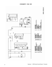
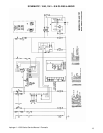
SEQUENCE OF OPERATIONS 1000/1001/1004/1005/1200/1201/1204/1205
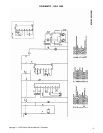
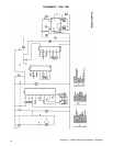
MODEL 1000 - 120/230 VAC - 60HZ - NATURAL GAS
MODEL 1001 - 120/230 VAC - 60HZ - L.P. GAS
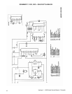
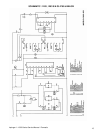
MODEL 1004 - 120/230 VAC - 60HZ - NATURAL GAS
MODEL 1005 - 120/230 VAC - 60HZ - L.P. GAS
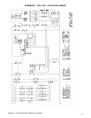
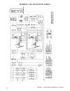
MODEL 1200 - 120/230 VAC - 60HZ - NATURAL GAS/DUAL BELT
MODEL 1201 - 120/230 VAC - 60HZ - L.P. GAS/DUAL BELT
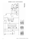
MODEL 1204 - 120/230 VAC - 60HZ - NATURAL GAS/DUAL BELT
MODEL 1205 - 120/230 VAC - 60HZ L.P.GAS/DUAL BELT
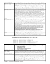
POWER SUPPLY Electrical Power to be supplied to the Oven by a four conductor service. . Voltage
from the black conductor to the white conductor is 120 VAC.
Black conductor is Hot
Red conductor is Hot
White conductor is Dedicated Neutral
Green conductor is Ground
CONTROL BOX AUTO
COOL DOWN
When the temperature in the Control Box reaches 120°F + 3°, the Cooling Fan
Thermostat will switch power to the Control Box Cooling Fan. The Thermostat will
interrupt power to the Cooling Fan when the Control Box temperature falls to 100°F +
3°.
MAIN FAN CIRCUIT Electrical power is permanently supplied to the normally open contacts of the Double
Pole Main Fan Relay, the Cooling Fan Thermostat, the normally open Main Fan
Switch, and the normally open Cool Down Thermostat (thermostat closes at 160°F
and opens at 140°F). Closing the Main Fan Switch energizes the coil of the Relay.
The normally open contacts now close, energizing the Main Fan Motor through (2)
10A fuses, and the Cooling Fan. Closing the Fan Switch also supplies power to the
Hour Meter (hour meter discontinued after S/N 3484), the 12.6 VAC Transformer, the
Burner and Conveyor Switches.
TRANSFORMER (12.6
VAC)
Upon closure of the Fan Switch, 120 VAC is supplied to the primary of the 12.6 VAC
Transformer. The Transformer steps the voltage down to 12.6 VAC (normally 13 to
14 VAC) with a center tap, and supplies power to the Time/Temp Display. The
voltage from each leg of the Transformer's secondary to the center tap should be
one half of the secondary voltage.
BURNER CIRCUIT Closing the Fan Switch and the normally open Burner Switch supplies 120 VAC
through the Air Pressure Switch, to the normally open contacts of the Burner Motor
Relay, and the primary of the 24 VAC Step Down Transformer. The Transformer
secondary supplies 24 VAC (through a 1A fuse on Model 1004 and 1005) to the
Relay Coil (the normally open contacts close within 30 seconds), and the normally
open Centrifugal Switch. When the Relay contacts close, the Burner Blower Motor is
energized. As this motor reaches approximately1600 R.P.M., its internal centrifugal
switch closes, supplying 24 VAC to the Gas Control Valve. When the Gas Control
Valve is supplied with 24 VAC the pilot valve is energized, and the ignitor circuit is
energized. Ignition should now occur. After pilot flame is proven, the main gas valve
is energized. The Burner Indicator Light is also energized.
CONVEYOR DRIVE(S/N
100 to 4389)
Closing the Fan Switch and the normally open Conveyor Switch supplies 120 VAC
through a 3A Fuse, to the Motor Control Board. AC volts are converted to D.C. volts
and are supplied to the Conveyor motor at board terminals A1 and A2 through a
D.P.D.T. Reversing Switch. Adjustment of the Speed Control Potentiometer (500
ohm, 10 turn) will change resistance at terminals S1, S2, and S3 varying the D.C.
voltage to the motor. The speed of the Conveyor Motor will increase or decrease as
the D.C. voltage from the Motor Control Board increases or decreases respectively.
(S/N 4390 and UP) Closing the fan switch and the normally open conveyor switch supplies 120 VAC to
the Motor Control Board. AC volts are converted to DC volts and are supplied to the
Conveyor Motor at terminals A+ and A-. Adjustment of the Speed Control
Potentiometer (5,000 ohm 10 turn ) will change resistance at terminals P1, P2, and
P3 varying the DC voltage to the motor. The speed of the conveyor motor will
increase or decrease as the DC voltage from the board increases or decreases
respectively. As the motor turns, it drives both the reducer gearbox and the tach.