


Impinger I -–1000 Series Service Manual - Domestic
51
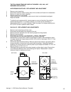
TEMPERATURE GAUGE - REPLACEMENT
1. Shut off power at main breaker.
2. Remove control panel top.
3. Disconnect thermocouple from temperature gauge.
4. Remove two (2) mounting bolts and remove temperature gauge.
5. Reassemble in reverse order.
THERMISTOR - REPLACEMENT
1. Shut off power at main breaker.
2. Remove control panel top.
3. Slide thermistor probe out of oven chamber.
NOTE: Remove conveyor and bottom fingers to aid in removal and instaliaticn of thermistor probe.
4. Disconnect wires from back of digital display at terminal strip (location #9-10).
5. Reassemble in reverse order making sure the probe is placed securely in the wire form in the oven
chamber.
6. Reconnect to digital display and calibrate. (See Time/Temperature Display - Replacement and
Calibration)
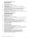
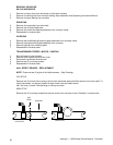
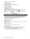
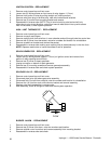
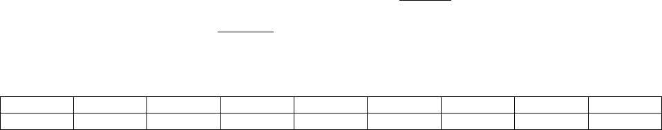
To test the thermistor probe, refer to the following chart and instructions
OVEN TEMPERATURE
300º F 325º F 350º F 400º F 425º F 450º F 500º F 550º F
OHMS 182 138 102 62 48 38 24 16
Place test pyrometer thermocouple and preheat oven as specified under temperature calibration.
Disconnect the thermistor probe from terminals 9 and 10 and measure the resistance across the 2 yellow
leads. Refer to the above chart to determine if probe is producing the proper resistance.
EXAMPLE: The probe resistance at 500°F(260°'C) should be 24 ohms.
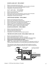
TRANSFORMER, TIME/TEMP. DISPLAY
1. Shut off power at main breaker.
2. Remove control panel top.
3. Remove relay box cover.
4. Disconnect two (2) wires at base of transformer and three (3) wires at terminals 1,2, and 3 on Time/Temp
Display.
5. Remove two (2) mounting screws.
6. Reassemble in reverse order.
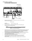
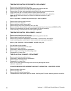
TIME/TEMPERATURE DISPLAY - REPLACEMENT & CALIBRATION
1. Shut off power at main breaker.
2. Remove control panel top.
3. Disconnect wires from rear of display. Make note of wire numbers and location for reinstallation.
4. Remove four (4) screws from display bezel (2 top/2 bottom) and remove display.
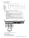
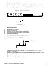
5. Install new display in reverse order. Note dip switch position and calibrate display as follows:
a) Check all wire connections to insure proper tightness.
b) Check dip switch setting to insure proper positions for the model of oven: