


Impinger I -–1000 Series Service Manual - Domestic
57
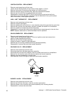
BURNER ALARM LIGHT - REPLACEMENT
1. Remove control panel top and front cover.
2. Remove two (2) wires from light assembly, note wire number and location.
3. Grasp body of light assembly and slide sideways to remove.
4. Reassemble in reverse order and check.
PILOT LIGHT (220V) - REPLACEMENT
1. Remove control panel top and front cover.
2. Remove switch access cover.
3. Remove two (2) wires from light assembly, note wire number and location.
4. Grasp body of light assembly and slide sideways to remove.
5. Reassemble in reverse order and check.
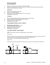
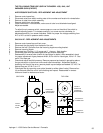
IGNITER SENSOR ASSEMBLY - REPLACEMENT
1. Remove control panel top and front cover.
2. Remove gas valve assembly (See Gas Valve)
3. Remove screws from burner tube and pull burner assembly out.
4. Remove wire connectors from igniter sensor assembly.
5. Remove screws from mounting bracket and remove assembly.
6. Reassemble in reverse order and check system operation.
NOTE: After installation, check all pipe fittings for leaks.
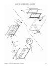
BURNER BLOWER MOTOR – REPLACEMENT
1. Remove control panel top and front cover.
2. Remove screws around blower tube.
3. Disconnect motor wiring and remove.
4. Reassemble in reverse order and check system operation.
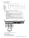
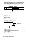
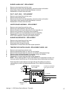
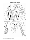
TEMPERATURE CONTROL BOARD - REPLACEMENT- MODEL 1030
1. Remove control panel top and front cover.
2. Remove potentiometer leads (3), note color and location.
3. Remove thermocouple leads (2), note color and location (white:pos/red:neg.).
4. Remove power and solenoid leads (4), note wire number and location.
5. Remove screw and board assembly and replace.
6. Reassemble in reverse order and check system operation.
NOTE: When replacing #369174 with (new) #369728, turn temperature control to its
maximum position and allow oven 30 minute preheat then calibrate board as follows:
Place temperature probe between top fingers #2 and #3 (making sure probe is
not touching any metal) and adjust potentiometer P6 to a Maximum temperature
of 575°F.
1
2
3
6
7
P 3
P 5P 6
11
10
9
L 1 120 VAC
L 2
LOAD
RED
BLACK
WHITE
+
-
THERMOCOUPLE
TYPE J
POTENTIOMETER
2.5 K OHMS
transformer marked with
green gold or silver dot