


Impinger I -–1000 Series Service Manual - Domestic
54
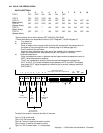
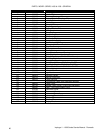
Dip Switch
1 2 3 4 5 6 7 8 9 10
TYPE I OFF OFF OFF ON OFF OFF
TYPE II OFF OFF OFF OFF OFF OFF
TYPE III OFF OFF OFF OFF OFF OFF OFF ON OFF ON
NOTE: When on 50 HZ power, dip switch #2 must be "ON"
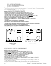
With power ON turn time and temperature cal. pot. fully counterclockwise.
Display should read: (Wait 15-20 seconds)
TYPE I 9:30 + 10 sec.475 + 10°F
TYPE II 9:20 + 10 sec. HHH
TYPE III 9:35 + 10 sec. 635 + 10°F
Turn time and temp. cal. pot. fully clockwise.
Display should read: (Wait 15-20 seconds)
TYPE I 10:20 + 10 sec. 615 + 10°F
TYPE II 10:10 + 10 sec. 475 + 10°F
TYPE III 10:20 + 10 sec. 475 + 10°F
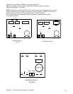
Turn time pot. to 10:00 minutes and temp. pot. to 540°F.
Time reading 10:00 ± 5 seconds.
Temperature reading should be steady at 540°F + 10°F.
If these readings are not achieved, replace display.
NOTE: After simulator test is completed, the oven Time/Temperature Display must be re-calibrated.
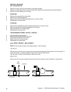
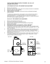
SWITCH REPLACEMENT (FAN, HEAT, CONVEYOR)
1. Shut off power at main breaker.
2. Remove control panel top and front cover.
3. Remove switch access cover.
4. Depress the spring clips on the sides of the switch and push out.
5. Remove wires from back of switch. Note wire number and location.
6. Install new switch in reverse order and check.
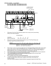
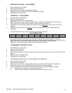
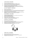
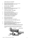
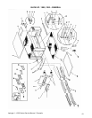
SWITCH REPLACEMENT - (FAN SWITCH UPDATE)
INSTALLATION OF DOUBLE POLE FAN SWITCH #369260 IN PLACE OF SINGLE POLE
FAN SWITCH #350705
NOTE: This change is not necessary for proper operation of oven nor is it
permissible to change under warranty. Should be changed only at
customer's request and their agreement to pay your bill.
ADVANTAGE: Allows time/temp. display, in older models, to operate same as current
production models. Also allows locked time/temp. display (caused by
voltage surge, interruption or spike) to be reset by fan switch rather than
circuit breaker.
IDENTIFICATION: To determine which fan switch you have, observe if temperature displays
stays on during cooling down. If it stays on , you have the single pole
switch. If it goes out as soon as fan switch is turned off you have the double
pole switch.
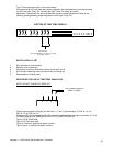
REPLACEMENT: Replace single pole switch # 350705.
Install double pole switch # 369260.
Disconnect lead indicated by # in proper diagram and reroute as shown.
Install jumper lead indicated by * in proper diagram.
Reapply all other leads as removed.