


Impinger I -–1000 Series Service Manual - Domestic
56
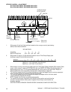
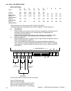
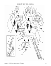
IGNITION CONTROL - REPLACEMENT
1. Remove control panel top and front cover.
2. Loosen two (2) locking screws on front cover of relay (approx. 1/2 turn).
3. Remove front portion of relay by pulling straight out (rocking motion).
4. Remove wires from plug-in terminal strip, note wire numbers and locations.
5. Remove two (2) screws from mounting bracket and remove.
6. Reassemble in reverse order (NOTE: Plug in terminal strip is polarized and will only
allow relay to plug in one direction, make sure manual reset button lines up with access
hole in front cover.) Check system operation.
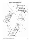
HIGH - LIMIT THERMOSTAT - REPLACEMENT
1. Remove control panel top and front cover.
2. Remove conveyor and fingers.
3. Remove capillary bulb from wire form in oven chamber and pull through tube into control box.
4. Remove two (2) wires from thermostat, note wire numbers and location for reinstallation.
5. Remove screws from bracket and remove thermostat.
6. Reassemble in reverse order making sure capillary tube is placed securely in the wire form.
NOTE: Depress reset button to insure thermostat is set for operation.
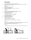
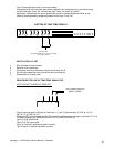
SPARK GENERATOR – REPLACEMENT
1. Remove control panel top and front cover.
2. Loosen two (2) locking screws (approx. 1/2 turn) on ignition control and remove front
portion of relay exposing terminal strip.
3. Remove two (2) wires for spark generator.
4. Unplug connector on bottom of spark generator.
5. Remove two (2) mounting screws and remove generator assembly.
6. Reassemble in reverse order and check system operation.
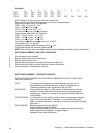
SOLENOID VALVE – REPLACEMENT
1. Remove control panel top and front cover.
2. Disconnect pipe union just above gas valve assembly.
3. Disconnect two (2) wires from solenoid, note wire number and location for reinstallation.
4. Remove four (4) nuts from main orifice burner bracket and remove assembly.
5. Replace valve and reassemble in reverse order.
6. After assembly, check all fittings for leaks and check system operation.
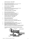
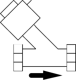
FLOW
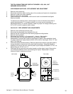
BURNER ALARM - REPLACEMENT
1. Remove control panel top and front cover.
2. Remove two (2) wires from alarm, note wire numbers and location.
3. Remove retainer cover from alarm and remove assembly from mounting bracket.
4. Reassemble in reverse order and check.