


Impinger I -–1000 Series Service Manual - Domestic
39
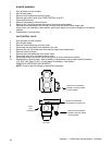
HEATING ELEMENT
1. Shut off power at main breaker.
2. Remove rear motor cover.
3. Disconnect heater element wire and mark for reassembly.
4. Remove oven back assembly.
NOTE: For ovens SN 4768 and above, remove fan shroud.
5. Remove two (2) mounting screws and remove heating element.
6. Reassemble in reverse order.
NOTE: Be sure the lead terminals are double nutted to the heating element and are tight
If the leads are not attached in this manner, a loose connection may result, causing
arcing and lead wire burn off.
IGNITION CONTROL
NOTE: When replacing Johnson Controls, G-60 or G-65 Ignition Control with the new Honeywell Ignition
control, the 24 VAC burner transformer (rated at 20VA) must be replaced with the larger (rated at 40VA)
#369531 Transformer.
1. Read all instructions supplied in kit before starting.
Tools required: Center punch and 7/32" drill bit.
2. Shut off power at main breaker.
3. Remove control panel top and front panel.
4. Remove front panel.
5. Remove ignition control package from Johnson gas valve and discard.
The white flame sensor wire, from the burner to terminal #4 on Johnson gas control
is no longer used. Cut Wire at burner and discard.
NOTE: On some Impinger ovens, it may be necessary to drill the mounting holes through the
oven specification plate. Use care to avoid drilling through any important
information or agency approval markings on the specification plate.
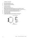
6. Use template supplied to locate and drill two (2) 7/32" mounting holes for new Ignition
Control. When mounting new ignition control, make certain that the green #67 ground
wire (supplied) is installed properly.
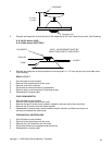
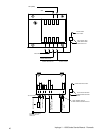
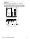
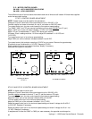
7. Connect wiring as follows:
Connect blue wire from gas valve to terminal marked P.V. on ignition control.
Connect black wire from gas valve to termainal marked M.V./P.V. on ignition control.
Connect red wire from gas valve to terminal marked M.V. on ignition control.
Connect white wire from indicator light to ground, by using splice connection on green
wire supplied.
Connect orange spark lead from burner to terminal marked "spark" on ignition control.
NOTE: It may be necessary to replace ignition cable terminal with .250" quick-
connect terminal (supplied).
Connect the red wire from burner blower motor centrifugal switch to terminal marked
24V on ignition control.
Connect green #68 wire (supplied) from terminal 24 GND to terminal GND (burner)
to ground.
Connect the green wire from 24VAC transformer to wire #68 at terminal marked
24V(GND) on ignition control.
The Honeywell ignition control module provides 100% safety lockout. Control will try for
ignition for 15 seconds. If ignition does not occur, control will lockout or shut off. To
reset control, the burner switch must be turned off for 1 minute.