


Impinger I -–1000 Series Service Manual - Domestic
4
generator. The tach. generator is a DC voltage generator which supplies a voltage to
the DC motor control board and is used as a reference for maintaining a constant
conveyor speed.
NOTE
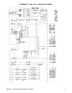
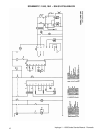
The 1200 Series Ovens utilize 2 complete conveyor drive systems.
TIME TEMP DISPLAY The Time/Temp. Display is energized when the Fan Switch is closed, supplying120
VAC to the primary of the 12.6 volt Transformer The secondary output of the
transformer, normally 13 to 14 VAC (depending on input), with a center tap is
supplied at terminals 1,2, and 3 of the Time/Temp. Display. The center tap is
terminal 2. The display works on a balanced input and center tap voltage to each leg
must be 1/2 the total reading.
The speed side of the Time/Temp. Display uses a slotted disc (cemented to tach.
coupling) to break the infra-red light beam of the optical switch (mounted on gear
motor) producing electrical pulses that are transmitted to the display. The display
converts these pulses into a read-out of minutes and seconds. The temperature
portion of the display uses a Thermistor Probe to sense oven temperature. The
thermistor outputs a resistance proportional to the oven temperature. This resistance
is then converted by the display into a temperature reading.
NOTE: The 1200 Series Ovens use a Double Pole Double Throw Switch to connect
the two Optical Encoder Assemblies to the Time/Temp Display. By activating the
switch, either the front or rear belt speed can be shown by the Time/Temp Display.
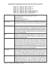
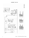
SEQUENCE OF OPERATIONS 1022 / 1023 / 1202 / 1203
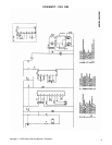
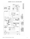
MODEL 1022 - 120/208 VAC - 3 PHASE
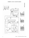
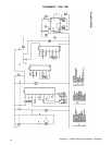
MODEL 1023 - 120/240 VAC - 3 PHASE
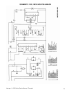
MODEL 1202 - 120/208 VAC - 3 PHASE - DUAL BELT
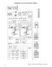
MODEL 1203 - 120/240 VAC - 3 PHASE - DUAL BELT
POWER SUPPLY Electrical Power to be supplied to the Oven by a five conductor service. Voltage from
the black conductor to the white conductor is 120 VAC.
Black conductor is Hot
Red conductor is Hot
Orange conductor is Hot
White conductor is Dedicated Neutral
Green conductor is Ground
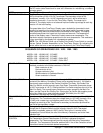
MAIN FAN CIRCUIT Electrical power is permanently supplied through 6, 50A fuses to the normally open
contacts of the Mercury Contactors. Power is also supplied through 2, 15A fuses to
the normally open contacts of the Double Pole Main Fan Relay, the Double Pole
Main Fan Switch, and the normally open Cool-Down Thermostat (thermostat closes
at 160°F and opens at 140°F.) Closing the Main Fan Switch energizes the coil of the
Main Fan Relay. The normally open contacts now close, energizing the Main Fan
Motor, and the Control Box Cooling Fan. Closing the Fan Switch also supplies power
to the Hour Meter (hour meter discontinued after S/N 3484), the 12.6 VAC
Transformer, the Heat and Conveyor Switches.
TRANSFORMER (12.6
VAC)
Upon closure of the Fan Switch, 120 VAC is supplied to the primary of the 12.6 VAC
Transformer. The Transformer steps the voltage down to 12.6 VAC (normally 13 to
14 VAC) with a center tap, and supplies power to the Time/Temp Display. The
voltage from each leg of the Transformer's secondary to the center tap should be
one half of the secondary voltage.
HEAT CIRCUIT Closing the Fan Switch and the normally open Heat Switch supplies 120 VAC
through the Air Pressure Switch and the normally closed Hi-Limit Thermostat
(manually re-settable, opens at 190°F) the 3A Fuse, to the L1 terminal of the
Temperature Control Board, the coils of the Mercury Contactors, and to the Heat
Indicator Light.
TEMPERATURE
CONTROL
When the Heat Switch is closed, 120 VAC is supplied to the Temperature Control.
The Temperature Control Potentiometer (2.5K ohm) is adjusted to desired
temperature. The Thermocouple will provide varying millivolts to the Temperature
Controller. The Temperature Controller switches the L2 line of the Contactor coils at
intermittent intervals to maintain desired temperature.