


Impinger I -–1000 Series Service Manual - Domestic
44
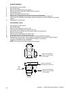
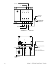
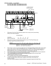
OPTICAL ENCODER ASSEMBLY
1. Shut off power at main breaker.
2. Remove conveyor motor assembly .If replacing with new assembly, cut wires to remove as new wires
and plug are provided. If only removing for access to coupling follow step 4.
3. Remove pins from connectors with pin extractor tool, P/N 369600.
4. Loosen dust cover screws and pull dust cover away from motor.
5. Remove 2 screws from optical encoder and remove encoder.
6. Reassemble in reverse order. To adjust optical encoder: Position the encoder assembly so it does not rub
the coupler hub and is square with the encoder disc. The infrared light beam will be broken by slots in the
encoder disc. The encoder disc should not touch the bottom or top of the optical encoder. If it does
readjust the coupling. The digital speed readout may be observed to check proper adjustment of the
optical encoder assembly.
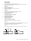
TACH. GENERATOR
1. Shut off power at main breaker.
2. Remove conveyor motor assembly .
3. Remove tach. cover plate and tach. Ieads. Mark lead position.
4. Remove 2 slotted screws from dust cover base and remove dust cover.
5. Loosen coupling set screw (.050 inch allen wrench).
6. Remove tach. bracket from motor.
7. Remove 4 screws from base of tach. and tach. is now free for removal.
8. Reassemble in reverse order. Maintain spacing of .010 minimum between tach. Bracket
and coupler hub.
NOTE: If a new tach. generator is installed, the D.C. motor control board MUST BE
RECALIBRATED There is no repair procedure for the tach. If defective, replace.
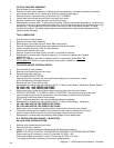
CONVEYOR MOTOR CONTROL BOARD
1. Shut off power at main breaker.
2. Remove control panel top and front cover.
3. Remove cover from relay box.
SN 100-4389 BODINE SYSTEM
Remove wires from terminal strip on control board making sure to mark wires so they
will be reinserted on the proper terminal.
Remove the four (4) hex head screws.
Reassemble in reverse order and calibrate (See D. C. Motor Control Board - Calibration, Bodine System)
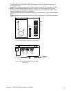
SN 4390-14974 1000 SERIES GAS OVENS
SN 4390-14791 1200 SERIES GAS OVENS
4. Make note of wire number and location before removing them from the control board.
POLARITY BETWEEN, T1-T2 AND A+ AND A- IS CRITICAL. The bottom mounting screw need
only be loosened as the mounting bracket for the control board is slotted. Remove top two
(2)mounting screws and remove control board.
NOTE: Exchange boards on the mounting bracket before reinstallation.
5. Reassemble in reverse order and calibrate (See D. C. Motor Control Board - Calibration)
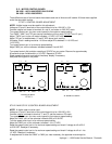
SN 14975 AND ABOVE 1000 SERIES GAS OVENS
SN 14792 AND ABOVE 1200 SERIES GAS OVENS
Make note of wire numbers and location before removing them from the control board.
6. The bottom mounting screw need only be loosened as the mounting bracket for the control
board is slotted. Remove top two (2) mounting screws and remove control board.
7. Reassemble in reverse order and calibrate. (See Stepper Control-Adjustment)
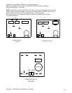
D. C. MOTOR CONTROL BOARD - CALIBRATION
SN 100 to 4389 - BODINE SYSTEM
1. Remove control panel top and front cover.
2. Remove cover from relay box.
3. Identify D. C. control board and calibrate as per the following instructions:
NOTE: THE USE OF A DIGITAL VOLTMETER IS NECESSARY FOR PROPER ADJUSTMENT
Check incoming AC voltage at L1 and L2. Should be 120 VAC ± 10%.
Check field voltage at terminals F1 and F2. Should be 100 VDC ± 10 volts.
Turn speed control dial clockwise to its maximum speed position.