


102
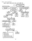
9. Component Checks Reset System After Lockout
If the oven enters safety lockout, the system must be
reset before attempting further operation or checkout.
The system will remain in safety lockout until it is re-
set. Shut system OFF. (Turn Heat switch OFF.) Wait
at least five minutes, then turn Heat switch ON.
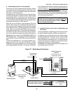
10. Check Spark Ignition Circuit
The electronic module and step-up transformer in the
ignition module provide spark ignition at 15,000V (open
circuit). This circuit can be checked at the ignition
module as follows:
a. Turn OFF the gas flow at the manual shutoff valve.
b. Disconnect the ignition cable at the ignition mod-
ule terminal to isolate the circuit from the pilot
burner/ignitor sensor, and prepare a short jumper
lead using heavily insulated wire, such as a spare
ignition cable.
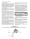
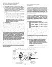
c. Energize the ignition module and touch one end of
the jumper firmly to the control board ground termi-
nal (GND). Do not disconnect the existing ground
lead. Move the free end slowly toward the stud
terminal to establish a spark and then pull the lead
wire slowly away from the stud. Note the length of
the gap at which arcing stops.
d. An arc length of 1/8 (3.2mm) or more indicates
satisfactory voltage output. Replace the ignition
module if no arc can be established or if the maxi-
mum gap is less than 1/8 (3.2mm), and power to
the ignition module input terminals was correct.
WARNING
Do Not touch either stripped end of jumper or stud
terminal. This is a very high voltage circuit and
electrical shock can result. Perform the test im-
mediately upon energizing the system, before the
ignition module enters safety lockout and inter-
rupts the spark circuit.
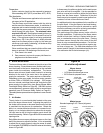
11. Check Spark Ignitor
If the troubleshooting procedure indicates a problem
with the ignitor/sensor, check the spark ignitor and the
ignition cable connections and continuity as follows:
Check Ignitor/Sensor
a. Check the ignitor spark gap to make certain it is
correct, 1/8 (3.2mm). If necessary, use a
needlenose pliers and carefully bend the tip of the
outer electrode to the correct gap.
b. Check that the pilot flame is properly adjusted.
Check Igniton Cable
a. The ignition cable must not touch metal surfaces
or current-carrying wires. Use ceramic standoff
insulators, if necessary.
b. Check the length of the ignition cable. It must not
exceed 3 ft. (0.9 m).
c. Check the connections to the ignitor and ignition
module terminals. All connections must be clean
and tight. Loose connections may not conduct a
flame current even though the ignition spark is sat-
isfactory. Check the electrical continuity of the
cable. Replace the cable if it is damaged or dete-
riorated.
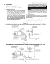
d. If no spark or a weak spark occurs, but the spark
ignition circuit checked normally, disconnect the
ignition cable at the ignitor/sensor and measure
the arc from the cable end to the ignitor stud. Fol-
low the same general procedures and observe the
same cautions as in Step 10, Check Spark Igni-
tion Circuit, above.
If the arc is correct, replace the ignitor/sensor.
If the arc is less than it should be, disconnect the igni-
tion cable and use a jumper wire from the ignition mod-
ule stud terminal. If the spark is normal, replace the
ignition cable. If the arc is still smaller than normal,
replace the ignition module.
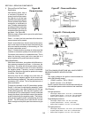
Q. Checking the Gas Pressures
All gas pressures should be checked using a manometer
at the supplied pressure taps, as follows:
Inlet pressure can be checked at the inlet pressure tap
on the combination gas valve. See Figure 72 (on Page
98).
Regulated pressure can be checked at the outlet pres-
sure tap on the combination gas valve. See Figure 72
(on Page 98).
Current PS555/570-series ovens provide an additional
regulated pressure tap in the main gas line, just before
the line enters the burner. This allows you to connect
a SECOND manometer downstream of the modulating
valve to check that the valve is functioning properly.
We encourage you to use this tap to diagnose prob-
lems with the modulating valve whenever possible.
Pilot gas pressure can be checked at the pilot pres-
sure tap. For ovens with a Wayne burner, the tap is
located on the pilot line. For PS360EWB/WB70 ovens
with a Midco burner, the tap is located on the end of
the pilot orifice fitting. Refer to the illustrations on Pages
88-90.
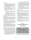
Some older ovens (pre-1994) with Wayne burners may
not be equipped with a pilot pressure tap. If you en-
counter problems with an erratic pilot (see Servicing
the Combination Valve on Page 98), it may be neces-
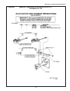
sary to install a tap. Middleby offers Service Kit P/N
30185 which includes the pilot pressure tap and in-
structions. A copy of the instructions are also provided
in the Appendices section.
IMPORTANT: Any older oven that has a pilot pressure
tap installed should have the combination gas valve re-
placed with a current version at the same time. Com-
bination valves used prior to 1994 are beyond the scope
of this Manual and may not be compatible with the tap.
SECTION 3 - SERVICING COMPONENTS