47
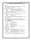
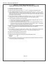
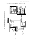
B. INSTALLATION
WARNING
BEFORE PERFORMING ANY SERVICE WORK, THE GAS SUPPLY (IF SO EQUIPPED)
AND
THE ELECTRICAL SUPPLY TO THE OVEN
MUST BE TURNED OFF.
1. Open the machinery compartment and control compartment access panels.
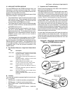
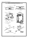
2. Locate the high limit thermo bulb/capillary assembly. Its location is shown in Figure 2. Loosen the set
screw that holds the assembly in place. Remove the thermo bulb/capillary assembly from the mount-
ing tube.
3. Disconnect the wires (2 for the Type 54 control, 4 for the Type 55 control) from the terminals of the
United Electric control. Bundle the loose wires together, and allow them to hang loose for later
reconnection.
4. Remove the mounting screws that hold the United Electric high limit control in place. Then, remove
and discard the high limit control and its mounting screws.
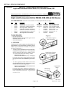
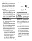
5. Position the new high limit control in place on the left wall of the control compartment, as shown in
Figure 3. When positioning the control:
Ensure that the control is positioned AT LEAST 1 (25mm) back into the compartment to allow the
compartment door to close.
Ensure that additional space is left underneath the control for the reset switch.
NOTE: Instead of holding the high limit control in place, you may use the dimensions provided in
Figure 4 to determine the location of the control and its mounting holes.
6. Mark the locations of the two mounting holes for the high limit control. Then, drill the holes using a
3/16 drill bit.
7. Secure the high limit control in place using the kit-supplied 6-32 x 1-5/8 screws and 6-32 nuts.
8. Position the bracket for the reset switch on the left wall of the control compartment, as shown in Figure
3. Note that the face of the bracket with the large, circular switch-mounting hole should face YOU.
Also, the bracket should be positioned AT LEAST 3 (75mm) back into the compartment to allow the
door to close.
9. While holding the bracket in place, mark the locations of the two mounting holes. Then, remove the
bracket and drill the holes using a 3/16 drill bit.
10. Secure the bracket to the panel using the kit-supplied 6-32 x 1/4 screws and 6-32 nuts. DO NOT
INSTALL THE RESET SWITCH INTO THE BRACKET AT THIS TIME.
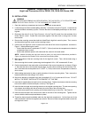
11. Insert the kit-supplied thermocouple into its mounting sleeve. Position the sleeve so that the mounting
hole is at the base of the thermocouple, not the tip. See Figure 5.
12. Insert the thermocouple and mounting sleeve into the original mounting tube. The set screw opening
in the sleeve should align with the set screw hole on the side of the mounting tube.
Push the thermocouple into the opening until its base seats firmly on the mount. See Figure 6.
13. Insert the thermocouples set screw into the hole on the side of the mounting tube. Tighten the set
screw to hold the thermocouple and sleeve in place.
14. Thread the thermocouples shielded cable into the electrical compartment. Coil the free end of the
cable and fasten it with the kit-supplied nylon wire tie. Be sure to leave enough free cable to reach the
new high limit control.
Page 2 of 8
SECTION 3 - SERVICING COMPONENTS
Appendix - Instructions for Service Kit 39733 -
High Limit Conversion Kit for PS300, 310, 350 & 360 Ovens, 5/99


