56
1
Instructions for Service Kits P/Ns 33984 and 33985
Oven Thermocouple Kit
Middleby Cooking Systems Group 1400 Toastmaster Drive Elgin, IL 60120 USA (847) 741-3300 FAX (847) 741-4406
This Service Kit provides the parts and instructions necessary to replace one temperature-sensing or high limit thermo-
couple in any of the following Middleby Marshall oven models:
P/N 34701 Rev. C V1 11/01
KIT CONTENTS - KIT P/N 33984
P/N Qty. Description
33812-1 1 Thermocouple, type J, 6 L
B301A8861 2 Screw, hex wshr hd #6 x 3/8
21292-0001 3 Screw, hex wshr hd #10-16 x 3/4
27276-0001 1 Cable clamp, nylon
41687 1 Attachment plate, PS360 rear thermocouple
34701 1 Instructions
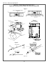
These instructions include replacement procedures for ovens built with the current flanged thermocouple, AND for ovens
built with the obsolete thermocouple without a flange (P/N 28071-0001).
PS200 Series uses Kit P/N 33985
PS360 Series uses Kit P/N 33984
PS536 uses Kit P/N 33985
PS555 uses Kit P/N 33984
PS570 uses Kit P/N 33984
IMPORTANT - READ THIS
BEFORE YOU BEGIN!
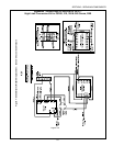
The thermocouple in your Kit has three leads:
The red and white leads connect directly to the thermocouple terminals on the ovens temperature controller (or high
limit control module, as appropriate), or to a local terminal block that in turn is connected to one of these units.
The uninsulated lead is a ground wire for the thermocouples protective sheath. The ground connection helps to drain
any radio-frequency disturbances from the thermocouple before the signal enters the temperature controller or high
limit control module. For a temperature-sensing thermocouple, the ground lead MUST be connected to the ground
terminal on the temperature controller. For a high limit thermocouple, the ground lead should be connected to a
chassis ground or to the mounting screw for the high limit control module.
Some early thermocouples may have either two or four leads:
The two-lead thermocouple is simply an earlier version of the current model, without the ground lead. When replacing
a two-lead thermocouple, it will be necessary to connect the new ground lead.
The four-lead thermocouple is actually a dual-function unit which sends its signal to both the temperature controller
and the high limit control module. Current ovens use separate thermocouples for these functions. When replacing a
four-lead thermocouple, it will be necessary to use a SECOND KIT to install the high limit thermocouple. In addition,
any oven equipped with these early thermocouples should have all of its thermocouples updated at the same time. For
a PS570 or PS570S oven, this will require THREE THERMOCOUPLE KITS - two for the existing thermocouples, and
one for the new, separate high limit.
PS200 Series - before 2/96, serial numbers before ASH-0001 ...........2
PS200 Series - 2/96 or later, serial numbers after ASH-0001 .............2
PS360 Series rear wall thermocouples - before 2/96, serial
numbers before ASH-0001.................................................................3
PS360 Series rear wall thermocouples - 2/96 or later, serial
numbers after ASH-0001.................................................................... 3
PS360 Series front-mounted thermocouples inside the
machinery compartment......................................................................4
PS536................................................................................................5
Oven Model Page
PS555 Gas - rear wall thermocouples with screw terminal
connections (no terminal blocks) .........................................................8
PS555 Electric and PS555E............................................................... 9
PS570 (X01-X05 name plate ID numbers) and PS570S
(early) with side-mounted thermocouples inside
or outside
the blower motor compartments ........................................................ 10
PS570S (late) - rear wall thermocouples with left-side AND
right-side terminal block connections .................................................12
PS555G and PS570G - rear wall thermocouples with
left-side terminal block connections ....................................................14
Oven Model Page
KIT CONTENTS - KIT P/N 33985
P/N Qty. Description
33812-2 1 Thermocouple, type J, 13-3/8 L
B301A8861 1 Screw, hex wshr hd #6 x 3/8
34701 1 Instructions
WARNING
BEFORE PERFORMING ANY SERVICE WORK, THE ELECTRICAL POWER SUPPLY
AND THE GAS SUPPLY MUST BE TURNED OFF.
D. Appendices
Appendix - Instructions for Service Kits 33984 and 33985 -
Oven Thermocouple Kit, 11/01
SECTION 3 - SERVICING COMPONENTS


