


99
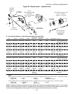
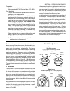
N. Ignition Module
1. Part Number Reference - Ignition Module
PS360WB70 and PS360EWB ovens equipped with the
Midco burner use Ignition Module P/N 31501.
For all other oven models:
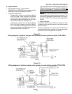
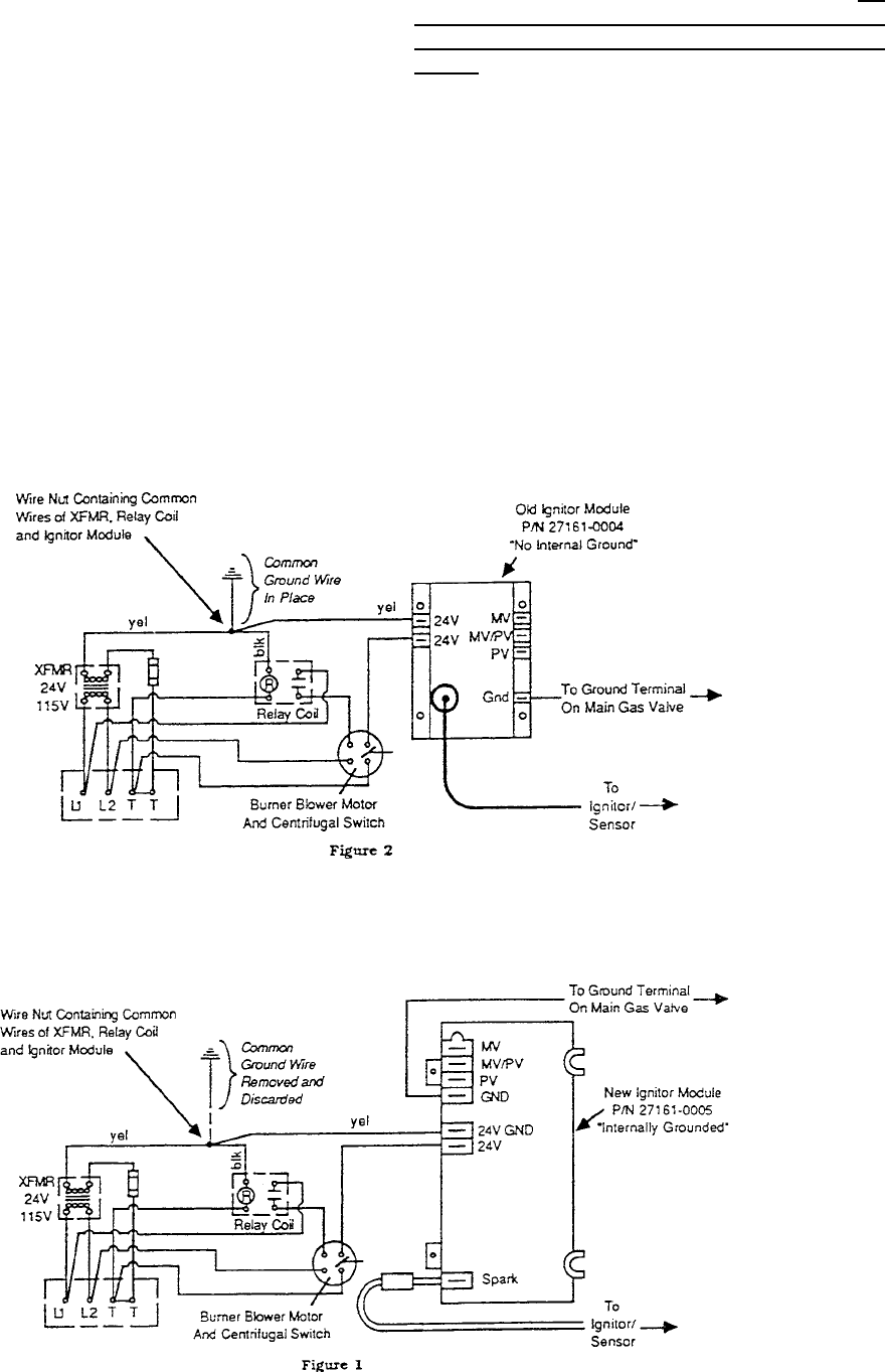
- Through 10/90 - these ovens used Ignition Module
P/N 27161-0004. Some versions of this module
included a separate, replaceable fuse. This mod-
ule shared a common ground with the 24V trans-
former and the relay coil. See Figure 73.
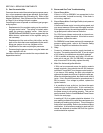
- 11/90 or later - these ovens use Ignition Module
P/N 27161-0005, included in Service Kit 42810-
0114. The module is internally grounded and the
common ground with the transformer and relay coil
has been eliminated. See Figure 74.
SECTION 3 - SERVICING COMPONENTS
If you are replacing the obsolete module (P/N 27161-
0004) with the current version (P/N 27161-0005), BE
SURE TO DISCONNECT THE MODULE FROM THE
COMMON GROUND WITH THE TRANSFORMER AND
RELAY. Double-grounding of the module creates a feed-
back voltage circuit that allows the module to operate
without a signal from the burner/blower assembly. This
procedure is explained in greater detail in the instruc-
tions for Kit 42810-0114, included in the Appendices
section.
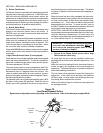
2. Module Operation
The ignition module delivers 24V to the pilot ignitor when
the blower motor centrifugal switch (or air pressure safety
switch) is closed.
When the module detects a current flow of at least 2.0 mA
through the pilot flame, it supplies 24V to the combination
gas control valve, allowing the valve to operate.
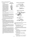
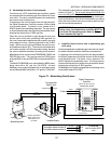
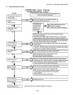
Figure 73
Wiring diagram of ignition and gas valve system (obsolete ignition module 27161-0004)
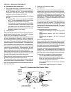
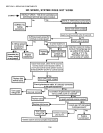
Figure 74
Wiring diagram of ignition and gas valve system (current ignition module 27161-0005)