


76
A. PS555/570-series ovens
All PS555/570-series ovens are equipped with two 1hp blower
motors. Each motor indirectly drives a pulley on the shaft
of a blower wheel with a fan belt.
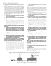
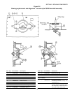
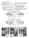
Two main designs exist for the PS555/570 blower fan sys-
tem:
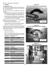
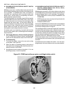
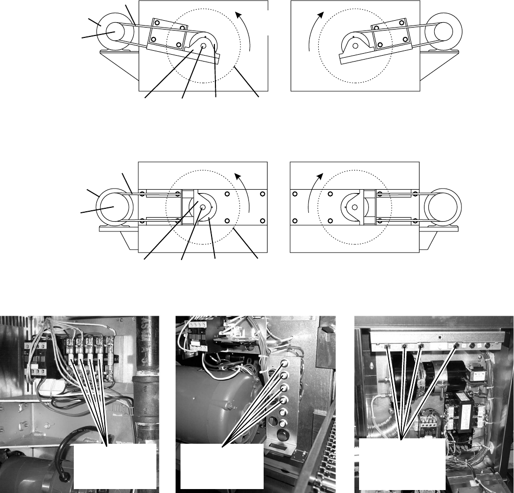
PS570/570S design. In this version, the pillow block
bearings for the blower wheel shaft were mounted up-
right, on brackets that were parallel to the fan belts.
See Figure 42.
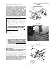
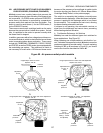
PS555/570G design. In this version, the pillow block
bearings are mounted with the grease fittings pointing
in towards the center of the oven. See Figure 43.
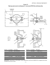
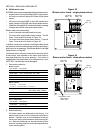
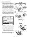
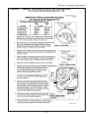
Figure 44 - Fuse/circuit breaker locations
PS570/570S:
15A fuses located on
left side of machinery
compartment
PS555 (early):
15A breakers located
inside left blower
motor compartment
PS555 (current),
PS570G: 15A
breakers located on
right side of machinery
compartment
The two designs share many common parts, including blower
wheels, motors, and bearings. From a service standpoint,
the major difference is the size of the pulleys and the length
of the belts.
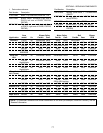
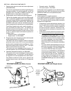
Blower motors on all PS555/570-series ovens are rated for
208-240V, single-phase, and are protected by:
A built-in thermal overload protection device.
Two 15A fuses or 15A circuit breakers. Refer to Figure
44 for the location of the fuses/breakers.
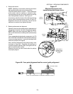
In addition, each blower fan is protected by an air pressure
saftety switch that prevents the burner/heating elements
from activating if the fan is not rotating. See Air Pressure
Safety Switch on Page 81.
Figure 42 - PS570/570S blower configuration
Figure 43 - PS555/570G blower configuration
Bearing PulleyBlower
shaft
Blower
motor
Pulley
Belt
Blower wheel
(inside oven)
Direction
of rotation
Bearing PulleyBlower
shaft
Blower
motor
Pulley
Belt
Blower wheel
(inside oven)
SECTION 3 - SERVICING COMPONENTS