


62
7
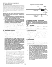
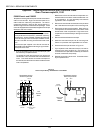
PS555 Electric and PS555E
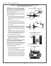
Temperature-sensing thermocouples on these ovens are lo-
cated on the rear wall. High limit thermocouples are lo-
cated inside the machinery compartment. All thermo-
couples are secured in place by two screws that are in-
serted through the holes in the thermocouple flange. These
ovens are equipped with a three-lead, flanged thermocouple
identical to the one in this Kit.
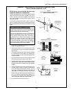
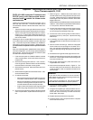
NOTE FOR HIGH LIMIT THERMOCOUPLES:
PS555E electric ovens are equipped with a high limit ther-
mocouple at the front of the oven, inside the machinery
compartment. All other PS555E, PS555G and PS570G
ovens have a high limit thermocouple installed into the
rear wall in the last mounting hole at the exit end of the
oven.
The thermocouple supplied in this Kit can be used to
replace ANY of the temperature-sensing or high limit ther-
mocouples on the oven.
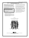
1. If you will be replacing the high limit thermocouple, open
the machinery compartment door.
To replace any other thermocouple, first remove the
rear shrouds. Then, remove the cover over the left blower
motor. This allows access to the thermocouples on
the rear wall, and to the terminal block inside the blower
motor compartment.
Note that all of the rear wall thermocouples are con-
nected to the terminal block inside the left blower mo-
tor compartment. It is not necessary to access the
right blower motor compartment.
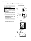
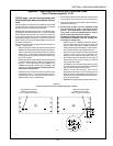
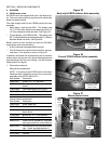
2. Remove the screws that hold the thermocouple to the
wall. Slide the thermocouple out of its mounting hole.
3. Disconnect the thermocouple leads. Rear wall ther-
mocouples are connected to the terminal block inside
the left blower motor compartment. High limit thermo-
couples are connected directly to the high limit control
module.
4. Remove and discard the thermocouple.
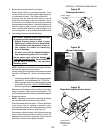
5. Install the new thermocouple into its mounting hole.
Fasten it in place with the supplied #6 x 3/8 screws.
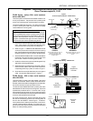
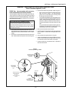
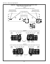
6. Wire the thermocouple as shown in Figure 10.
7. If you replaced a rear wall thermocouple, use the kit-
supplied nylon clamp and #10-16 x 3/4 screw to se-
cure the thermocouple leads so that they will clear the
shrouds, blower belts, and pulleys.
8. Replace all shrouds onto the oven. Close the machin-
ery compartment door.
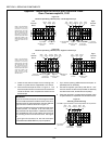
Figure 10
Thermocouple Wiring - PS555 Electric and PS555E
High Limit
Control
Module
Shielded
ground lead
Red White
Ground
leads
WhiteRed
Left
Terminal
Block
To temperature
controller
To ground
terminal on temp
controller
Temperature-sensing
thermocouple leads
Temperature-sensing
thermocouple leads
Appendix - Instructions for Service Kits 33984 and 33985 -
Oven Thermocouple Kit, 11/01
SECTION 3 - SERVICING COMPONENTS