13
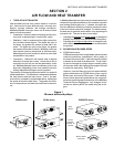
SECTION 3 - SERVICING COMPONENTS
SECTION 3
SERVICING COMPONENTS
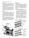
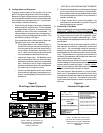
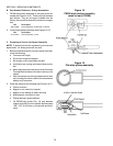
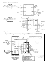
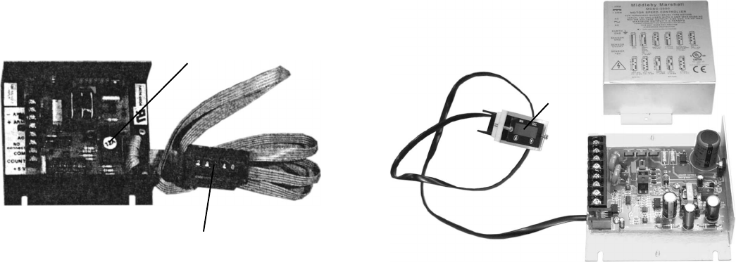
Figure 12
Original-style speed controller
Produced with thumbwheel only.
Interchangeable microcomputer selects oven model.
THIS CONTROLLER IS OBSOLETE AND NO
LONGER AVAILABLE.
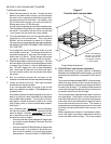
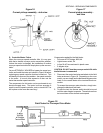
Figure 13
Current-style speed controller
Produced with Thumbwheel or digital display.
4 or 8 DIP switches select oven model.
Microcomputer
Thumbwheel
Control module
Thumbwheel
or digital
display
Control
module
DIP switches may
be on control
module or digital
display, depending
on the controller
model.
Cover plate
shows DIP
switch settings
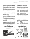
I. CONVEYOR SPEED CONTROLLER AND DRIVE
MOTOR
The Conveyor Speed Controller is used to set and monitor
the speed of the conveyor. The Controller consists of three
components:
Control Module
Early units used a module which featured a microcom-
puter that was unique to each oven model. Using this
control module required verifying that the correct mi-
crocomputer was installed.
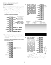
Later units use DIP switches to set up the controller for
a particular oven model. This later model was initially
available with a thumbwheel unit (either 4 or 8 DIP
switches). Current models feature a digital display with
keypad (8 DIP switches).
Thumbwheel Unit (or Digital Display with Keypad)
This module displays the conveyor speed and allows it
to be adjusted by the operator. It is connected to the
control module by a ribbon cable.
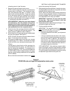
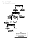
Pickup Assembly
The pickup assembly consists of a magnetic wheel on
the end of the gear motor (conveyor drive motor) shaft,
and a Hall Device sensor that provides feedback to the
control module.
As the magnetic wheel turns, the revolutions of the
magnet are monitored by the Hall Device sensor. The
signals are sent to the control module, which compares
the motor speed with the speed shown on the
thumbwheel or digital display. The control module in-
creases or decreases the voltage to the gear motor
(conveyor drive motor) depending on the signal.
A. Part Number Reference - Speed Controllers
1. Original-style speed controller with interchangeable mi-
crocomputer and thumbwheel. This unit is no longer
available and part numbers are provided for reference
only. Servicing this unit is beyond the scope of this
manual. If this controller is in need of service, we rec-
ommend simply installing a current unit (see below).
P/N Description
28174-0004 PS360 controller, yellow (12A) microcomputer
28074-0006 PS360 microcomputer, yellow (12A)
27170-0232 PS360 microcomputer w/emulator, yellow (12A)
28074-0007 PS314 controller, orange (13A) microcomputer
28074-0008 PS314 microcomputer, orange (13A)
27170-0233 PS314 microcomputer w/emulator, orange (13A)
28074-0013 PS200 microcomputer, pink (15A)
2. Current-style speed controller with either 4 or 8 DIP switch
settings and thumbwheel. This unit is no longer available
from the factory, but may still be stocked by service agen-
cies.
P/N Description
42810-0133 Controller assembly with thumbwheel
42810-0118 Thumbwheel only
3. Current-style speed controller with 8 DIP switch set-
tings and digital display/keypad. Note that the two types
of controllers ARE NOT compatible - the controller and
display unit MUST be of the same type.
P/N Description
37337 Controller assembly with digital display/keypad,
NCC (8/00-current)
37503 Digital display/keypad unit only, NCC
45133 Controller assembly with digital display/keypad,
Danaher (2/02-current)


