


57
2
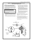
PS200 Series - before 2/96, serial numbers
before ASH-0001
Thermocouples on these ovens are located inside the ma-
chinery compartment. They are secured in place by a set
screw in the mounting tube, inside the plenum chamber.
This Kit eliminates the set screw. The new thermocouple
is held in place by the head of the screw that is already
used to attach the mounting tube.
NOTE FOR HIGH LIMIT THERMOCOUPLES:
CE ovens and PS200VL models have two thermocouples,
one mounted above the other. In these ovens, the upper
thermocouple senses the oven temperature and is con-
nected to the temperature controller. The lower thermo-
couple is connected to the high limit control module. Ei-
ther thermocouple can be replaced using this Kit.
1. Remove the lower end plug from the control end of the
oven. Then, remove 1 or 2 lower air fingers as neces-
sary to access the thermocouple mounting tube.
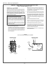
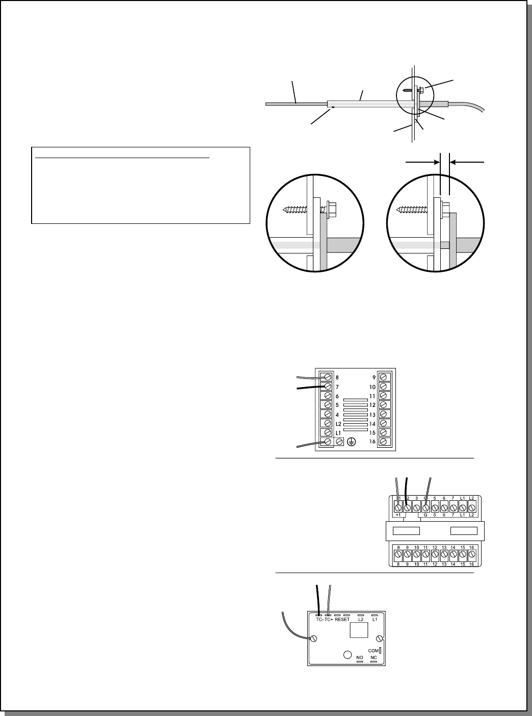
2. Refer to Figure 1. REMOVE AND DISCARD the set
screw and pull the thermocouple out of the mounting
tube. Disconnect the thermocouple wiring from the tem-
perature controller or high limit module, as appropriate.
3. Remove AND RETAIN the #10-16 screw that fastens
the flange of the thermocouple mounting tube to the
plenum wall. Leave the mounting tube in place.
4. Install the new thermocouple so that its flange fits firmly
against the mounting tube flange.
5. Replace the #10-16 screw that you removed in Step 3.
Check that the head of the screw holds the thermo-
couple flange securely in place, as shown in Figure 1.
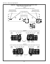
6. Route the thermocouple leads away from the ignition
cable. Connect the leads as shown in Figure 2.
PS200 Series - 2/96 or later, serial numbers
after ASH-0001
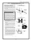
Thermocouples on these ovens are located in the same
position as the earlier PS200 models described above.
However, these ovens feature a flanged thermocouple iden-
tical to the new thermocouple provided in this Kit.
The thermocouple SHOULD be held in place by the screw
that attaches the thermocouple mounting tube, as per the
replacement procedure above. For these ovens, simply
disconnect the thermocouple wiring from the temperature
controller and follow Steps 3-6 of the procedure shown above
to remove and replace the thermocouple.
On some of these ovens, the thermocouple flange rests
ON TOP of the retaining screw for the mounting tube, as
shown in the INCORRECT inset of Figure 1. These ther-
mocouples are held in place by the set screw on the mount-
ing tube, inside the plenum chamber. For these ovens, you
should remove and replace the thermocouple by following
Steps 1-6 of the preceding section.
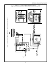
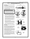
Figure 1
Thermocouple Installation - PS200 Series
Thermocouple
Mounting
tube
Set screw
(not used with new
thermocouple)
Mounting
tube
screw
Tube
flange
Thermocouple
flange
Oven
wall
CORRECT
Thermocouple flange sits firmly on
mounting tube flange; tube
mounting screw holds thermo-
couple in place.
INCORRECT
Thermocouple flange sits on top of
screw head, leaving a gap as
shown.
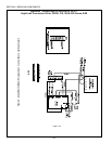
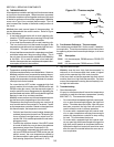
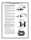
Figure 2
Thermocouple Wiring - PS200 Series
Digital
Temperature
Controller
Analog
Temperature
Controller
Red
White
Shielded
ground lead
RedWhite
Shielded
ground lead
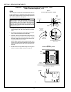
High Limit
Control
Module
Shielded
ground lead
Red White
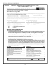
Appendix - Instructions for Service Kits 33984 and 33985 -
Oven Thermocouple Kit, 11/01
SECTION 3 - SERVICING COMPONENTS