


6
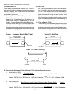
ll. ELECTRIC OVEN SEQUENCE OF OPERATION
A. Electrical Supply
Most electrically heated ovens operate on a 208/230/
380/440V, 3 phase, 4 wire system. The fourth wire is
for a 120 V neutral ground. This 120 V neutral ground
eliminates the need for a control transformer. Where a
neutral is not available, a 240/110V transformer is sup-
plied.
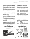
B. Door Switch
Closing the control cabinet door (or machinery com-
partment door, as appropriate for the oven model) will
close the door switch and allow the oven to operate.
Note that the electrical systems will still be live
if the switch is open, although the oven cannot
operate.
The door switch has a bypass position to enable ser-
vice operation with the door opened. When the door is
open, grasp the switch actuator and pull it out as far as
possible. This will close the door switch and permit
troubleshooting. Closing the control cabinet door will
reset the switch.
Closing the door switch permits a circuit to go through
a fuse (or circuit breaker, as appropriate for the oven
model) to one side of the conveyor switch, blower mo-
tor switch and to the heat switch.
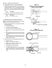
C. Conveyor Switch
Closing the conveyor switch permits a circuit to go to
the Conveyor Speed Control Module, which:
1. Sends power to the gear motor (conveyor drive mo-
tor). The 120VAC signal to the Conveyor Speed
Control Module is rectified to a 90VDC signal which
is then sent to the gear motor.
2. Allows regulation of conveyor speed. Adjusting the
thumbwheel (or digital pushbutton display unit, as
appropriate) to the desired conveyor belt speed in-
structs the Conveyor Speed Control Module to regu-
late the output to the gear motor. This increases
or decreases the conveyor speed as necessary to
match the speed setting shown on the thumbwheel
or display unit.
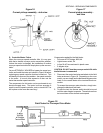
D. Blower Switch
Closing the blower switch energizes:
1. The cooling (axial) fan(s).
2. The blower motor contactor (s).
Closing this contactor starts the blower motor(s). When
both blower motors are up to speed, centrifugal
switch(es) located inside the rear end of the motor(s)
(or air flow switch[es], as appropriate for the oven model)
will close, setting up the heat circuit.
3. The Temperature Controller.
E. Heat Switch
Closing the heat switch completes a circuit:
1. Through the heat switch.
2. Through the blower motor centrifugal switch.
3. Through the high limit switch.
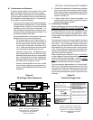
4. For ovens with on On-Off heater activation mode:
To the primary relay contacts of the Temperature
Controller (terminals 4 and 5 for digital controllers,
terminals 5 and 6 for analog controllers).
When the temperature-sensing thermocouple(s)
indicate that the oven temperature is below the set
point on the Temperature Controller, the Tempera-
ture Controller will energize the contactor(s) which
in turn energize the heaters.
When the oven temperature reaches the set point
of the Temperature Controller, the Temperature Con-
troller will cut power to the heaters. When the tem-
perature drops a few degrees, the Temperature Con-
troller will again energize the heaters.
An indicator on the Temperature Controller will
show whether the Controller is calling for heat. This
indicator varies by Temperature Controller model.
Refer to the instructions for the appropriate Tem-
perature Controller for an illustration and descrip-
tion of this indicator.
5. For ovens with a Variable Pulse heater activation
system: To terminals 15 and 16 on the tempera-
ture controller. In response to the signal from the
thermocouple(s), Terminals 15 and 16 send a 4-
20mA signal to a controller module that contains
an amplifier board and two solid state relays. The
relays activate the heating elements at 100% power
on a fixed cycle time, for a length of time propor-
tional to the signal from the temperature controller.
A HEAT ON indicator on the Temperature Con-
troller will light to show whether the Controller is
calling for heat.
F. High Limit
NOTE: Electric oven models use a separate High Limit
Control Module.
The High Limit relay will shut the oven burner OFF:
1. If the high limit thermocouple senses an oven tem-
perature above 650°F.
2. If the signal from the high limit thermocouple is
lost.
An indicator on the Temperature Controller will show a
high limit condition. This indicator varies by Tempera-
ture Controller model. Refer to the instructions for the
appropriate Temperature Controller for an illustration and
description of this indicator.
G. Cooldown
When the heat and blower switches are turned OFF
the cooldown relay will allow the blowers to remain ON
until the oven temperature falls to 200°F (93°C).
During cooldown, the Temperature Controller will con-
tinue to show the oven temperature.
SECTION 1 - SEQUENCE OF OPERATION