


37
Page 5 of 10
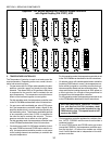
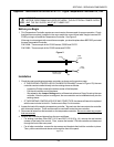
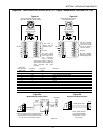
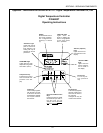
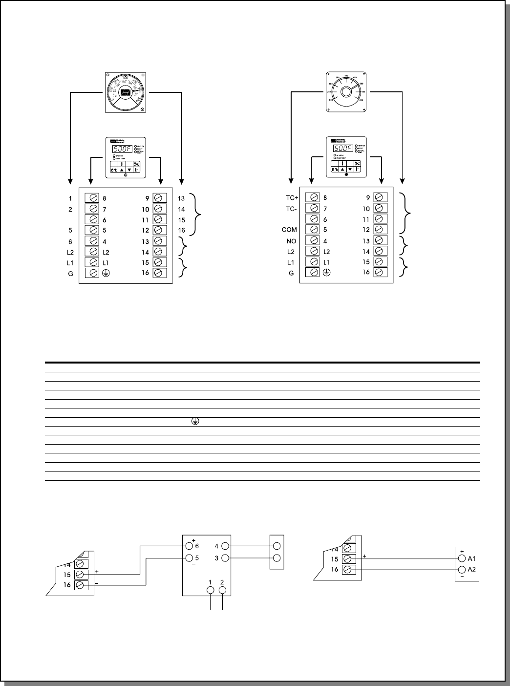
Figure 4a
Analog temperature controller (P/Ns
28071-0012 and 28071-0018) terminals
New temperature
controller terminals
Not used. These
terminals provide PID
output (gas ovens
with modulating
valve) or variable
Not used on
some gas and
electric ovens
Not used
Not used
Analog temperature controller
(P/N 34983) terminals
New temperature
controller terminals
Not used. PS200VL
ovens do not include a
modulating gas system.
Not used. PS200VL
ovens have a sepa-
rate high limit module
and do not include a
cooldown feature.
Not used
Not used
Figure 4b
pulse output (electric ovens with
variable pulse system). Neither of
these systems were available with
ovens equipped with these
controllers.
Terminal for
28071-0012 and Terminal for Terminal for Description
28071-0018 34983 46837
1TC+8 + TC
2TC-7 - TC
5 COM 5 Input to Temperature Control Relay
6 NO 4 Output to High Flame Solenoid or Heater Contactors
L2 L2 L2 Neutral
L1 L1 L1 Power
GG Ground
13 -- 9 Input to Cooldown Relay
14 -- 10 Output from Cooldown Relay
15 -- 11 Input to High Limit Relay
16 -- 12 Output from High Limit Relay
-- -- 15 PID or Variable Pulse Output
-- -- 16 PID or Variable Pulse Output
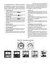
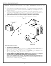
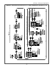
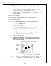
Figure 5a
Modulated Gas Output System
Figure 5b
Variable Pulse Output System
Amplifier board
Modulating
valve
24VAC
input
4-20mA
input
0-24VDC
output
20VDC pulsed output
Relay
NOTE: Safety switches
may be placed between
the temperature controller
and the relay on some
oven models.
NOTE: Controller P/N 32571 used Terminals 4 & 5
for the 4-20mA input to the amplifier board.
These connections must be moved to Terminals
15 & 16 on the new controller as shown.
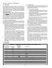
SECTION 3 - SERVICING COMPONENTS
Appendix - Instructions for Service Kit 47321 - Digital Temperature Controller Kit, 2/02