94
3. Pilot and Proof of Pilot Flame
Rectification
With standing pilots, heat is
a necessary ingredient for
proper thermocouple opera-
tion. But this is not the case
with IIDS (Intermittent Ignition
Device Systems) when flame
conduction or rectification is
used. To better understand the
principles of flame conduction
and rectification, we must first
understand the structure of a
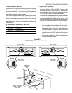
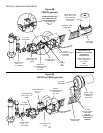
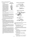
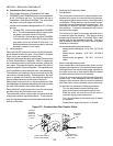
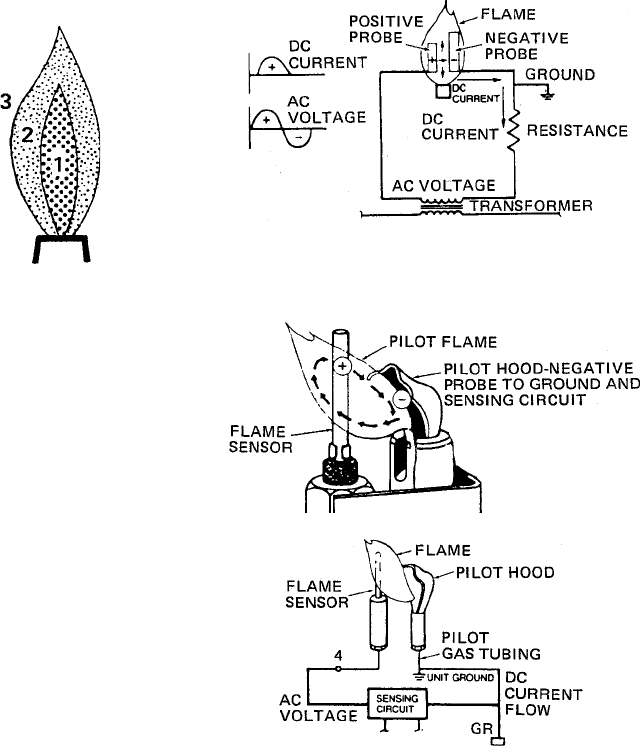
gas flame. See Figure 66.
Figure 66
Flame structure
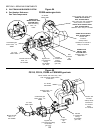
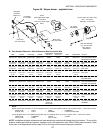
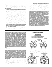
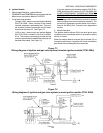
Figure 67 - Flame rectification
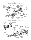
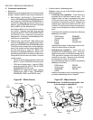
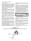
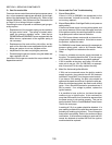
Figure 68 - Pilot and probe
SECTION 3 - SERVICING COMPONENTS
THE FOLLOWING CONDITIONS WILL HAVE A DIRECT
BEARING ON EVERY IID APPLICATION:
Voltage
The supply voltage to the ignition controls should be
within the following ranges:
120VAC controls 102 to 132VAC
24VAC controls 21 to 26.5VAC
24VAC systems should use transformers that will pro-
vide adequate power under maximum load conditions.
Gas Pressure
Inlet gas pressures
Natural gas, Wayne burner - 6-12 W.C. (14.9-29.9 mbar)
Propane, Wayne burner - 11½-12 W.C. (28.7-29.9 mbar)
Midco burner (all gases) - 6-14 W.C. (14.9-34.9 mbar)
Regulated gas pressures
Natural gas, Wayne burner - 3.5 W.C. (8.7 mbar)
Propane, Wayne burner - 10 W.C. (24.9 mbar)
Midco burner (all gases) - 3-5 W.C. (7.5-12.5 mbar)
Pilot gas pressures
Natural gas, Wayne burner - 3½-4 W.C. (8.71-9.95 mbar)
Propane, Wayne burner - 8-10 W.C. (19.9-24.9 mbar)
Midco burner (all gases) - 5-6 W.C. (12.5-14.9 mbar)
With the proper air-gas ratio to give a blue pilot flame,
three zones exist.
Zone 1: An inner, fuel-rich cone that will not burn be-
cause excess fuel is present.
Zone 2: Around the inner, fuel-rich cone is a blue enve-
lope. In this area is a mixture of vapor from the fuel-rich
inner cone and the secondary, or surrounding, air. This
is where combustion occurs.
Zone 3: Outside the blue envelope is a third zone that
contains an excessive quantity of air and will not burn.
Of concern is the second, or combustion area. This is
where the burning occurs and is the area that is of
prime importance for good flame sensor location.
Flame Rectification
With flame rectification, two probes with different sur-
face areas are exposed to a flame - in this case, the
pilot flame. The probe with the larger surface area at-
tracts more free electrons and, as a result, becomes
the negative probe. Therefore, current is conducted
through the flame from the positive probe to the nega-
tive probe. See Figure 67.
Note also that the AC voltage sine wave has not
changed, but the negative portion of the current sine
wave has been chopped off. This positive portion now
represents a DC current. This is the phenomenon of
flame rectification.
To apply this principle to an IID (Intermittent Ignition
Device - in this case, the pilot/ignitor assembly), a pilot
and flame sensor have been substituted for the two
probes (See Figure 68). After the pilot is ignited, a DC
current flow of 2.0mA (microamps) or more is conducted
through the flame, from the flame sensor (the positive
probe) to the pilot tip (the negative probe). The pilot tip,
acting as the negative probe, completes the circuit to
ground. The IID sensing circuit uses this DC current
flow to energize a relay and open the main burner gas
valve.


