


36
Page 4 of 10
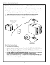
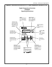
5. Check that the new controller is mounted into its sleeve. Then, slide the assembly into the opening in
the panel from the outside. Check that the controller is upright, with the display on top and the
keypad on the bottom.
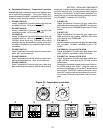
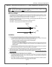
6. Locate the rectangular holes on the top and bottom of the new controllers sleeve. Attach the two kit-
supplied mounting brackets against the inside panel of the oven, and into the holes in the sleeve, as
shown in Figure 3. Check that the heads of the screws point to the rear of the controller.
7. Tighten the two screws evenly until the lip of the sleeve is seated tightly against the panel.
8. If there is a protective clear plastic strip on top of the display, remove it at this time.
Figure 3
Control
panel
Temperature controller is
pre-installed into sleeve
and is upright
Bracket clips and
screw heads point to
REAR of controller
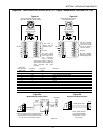
Electrical Connections
1. Wire the new controller as follows:
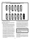
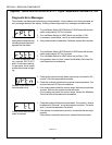
If you are replacing an Analog Temperature Controller, P/Ns 28071-0012 or 28071-0018 (see
Fig. 1A), refer to Figure 4A for a listing of the new terminal numbers.
If you are replacing an Analog Temperature Controller P/N 34983 (Fig. 1B - PS200VL models
only), refer to Figure 4B for a listing of the new terminal numbers.
If you are replacing any Digital Temperature Controller, simply reconnect ALL of the original
wires and jumpers to the same terminals, as all terminals are numbered the same.
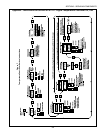
EXCEPTION: Controller P/N 32571(Fig. 1E - used on early PS360EWB ovens only) uses Termi-
nals 4 & 5 for the mA output to the amplifier board. The current controller uses Terminals 15 & 16 for
these connections, as shown in Figure 5A.
SECTION 3 - SERVICING COMPONENTS
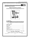
Appendix - Instructions for Service Kit 47321 - Digital Temperature Controller Kit, 2/02