


22 Function of the System
3
ot detcennoc eb tsum rosnes HR ehT
the PCB panel in the electronics casing
on the top of the MTD-ERV 350 by the
installer.
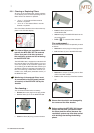
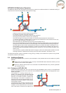
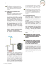
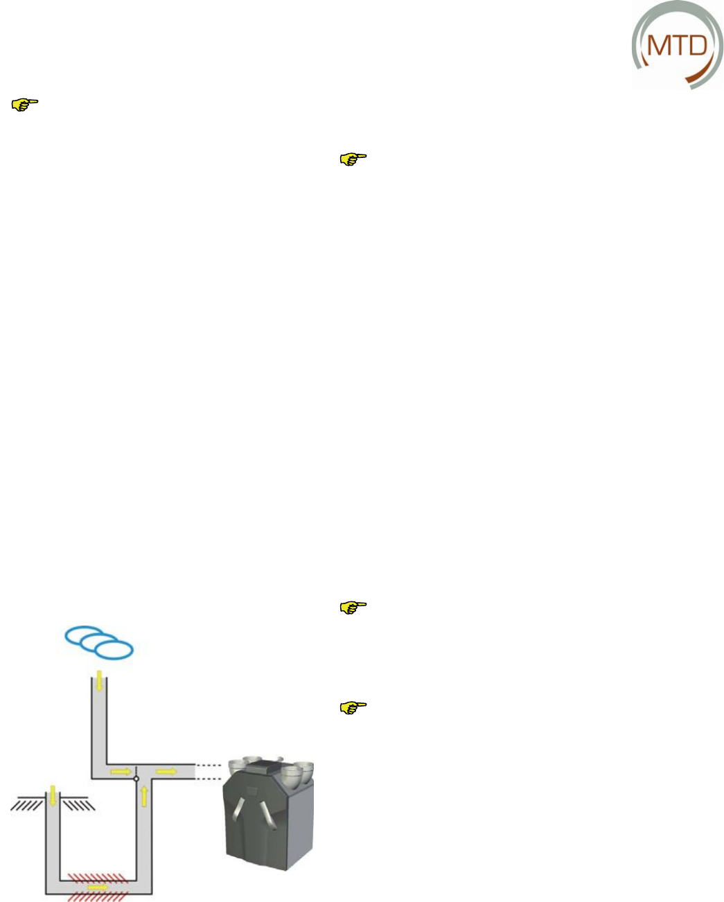
3.4.6 Underground Geothermal Heat
Exchanger*
As an option, the ventilation system can also be
equipped with a geothermal heat exchanger.
The geothermal heat exchanger is an addition-
al underground air duct at a depth of at least 1
metre and with a length of 20 to 40 metres that
forms part of the ventilation system. The geo-
thermal heat exchanger allows the outside air to
be admitted to the house under ground instead
of above ground. The heat of the soil is thereby
given off to the outside air as it fl ows through the
geothermal heat exchanger.
The geothermal heat exchanger is thus an out-
standing solution both in winter and in summer.
In frosty weather, the outside air can be heated
by the underground geothermal heat exchanger
before it enters the house via the MTD-ERV 350.
During hot weather in the summer, on the other
hand, the outside air can be cooled by the un-
derground geothermal heat exchanger before it
enters the house via the MTD-ERV 350.
The geothermal heat exchanger functions au-
tomatically. A temperature sensor installed any-
where on the outside of the house measures
the temperature of the outside air. As soon as
the temperature of the outside air is between 0
and 15
o
C in winter months and between 10 and
25
o
C in summer months, the geothermal heat
exchanger is activated to allow the outside air to
fl ow through the heat exchanger. The user can-
not infl uence the automatic geothermal heat ex-
changer control system. The installer simply has
to indicate whether or not a geothermal heat ex-
changer has been integrated into the ventilation
system in menu P60 of the CC Ease operating
unit during installation of the MTD-ERV 350 (for
further information, see section 4.4). The installer
can modify the automatic control of the geother-
mal heat exchanger to a slight extent in menu
P61 at the CC Ease operating unit, if necessary.
ehtdnaregnahcxetaehlamrehtoegehT
corresponding temperature sensor must
be connected to the PCB panel (extend-
ed version) of the MTD-ERV 350 by the
installer.
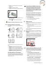
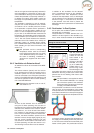
3.4.7 Chimney Sweep Control
Apart from the chimney sweep control set as
standard in the software, an additional unit can
be connected to the PCB panel (extended ver-
sion) of the MTD-ERV 350 as an option that can
switch off the fans of the MTD-ERV 350 via a float-
ing contact.
By means of a pressure sensor installed in the
room in which the hearth to be monitored is in-
stalled, the unit measures the pressure in the
room with the hearth. The pressure in the room
in which the hearth is installed and the adjacent
rooms must not exceed - 4 Pa so that fumes and
smoke cannot enter the house. At a pressure
higher than - 4 Pa, the fans of the MTD-ERV350
are switched off. Malfunction code "E4" appears
on the display. In this case, please contact the
installation company that installed the pressure
sensor and/or the heating. There is probably a
problem with the discharge of the fumes from the
hearth.
-dnopserroc eht dna tinu lanoitidda ehT
ing pressure sensor do not belong to the
standard scope of supply of the MTD-
ERV 350.
-dnopserroc eht dna tinu lanoitidda ehT
ing pressure sensor must be connected
to the PCB panel (extended version) of
the MTD-ERV 350 by the installer.
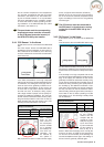
The installer cannot infl uence the automatic chim-
ney sweep control system. It reacts to settings at
the PCB panel (extended version) stored in the
software. The installer simply has to indicate
whether or not a chimney sweep control system
has been integrated into the ventilation system in
menu P50 of the CC Ease operating unit during
installation of the MTD-ERV 350 (for further infor-
mation, see section 4.4).