


5
5 - 17
W-2WAY ECO-i SYSTEM
Trouble Diagnosis
4. W-2WAY ECO-i Alarm Codes
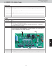
H11, H12 Alarm
Alarm code H11, H12
Alarm meaning H11: Constant speed compressor 2 overcurrent alarm
H12:
Constant speed compressor 2 lock current alarm
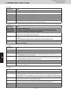
Alarm conditions H11: During operation, the compressor current value exceeded 20 A for 30 seconds or longer.
However this alarm is not detected for 4 seconds after the compressor starts.
H12: During operation, the compressor current value exceeded 29 A for 4 seconds or longer.
However this alarm is not detected for 2 seconds after the compressor starts.
Probable cause (1) Compressor failure (locked or partially locked)
(2) CT circuit failure (including cut wiring)
(3) Missing power phase
(4) Low power voltage
(5) PCB failure
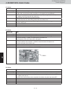
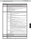
Check (1) Compressor failure (partially locked)
Trouble: Current value during operation greatly exceeds the value shown above.
Check: When the current for each phase is measured with a clamp meter or similar
instrument, check that the current value for all phases is not high. If MG was forced
ON (use caution), check that compressor noise will not occur or the compressor will
not run with a groaning sound.
(2) CT circuit failure, PCB failure
Trouble:
Check: • Check for poor connector contact.
Check the continuity of the CT circuit.
Install a normal CT in place of this CT and check. If current is detected, then the
PCB can be jedged OK.
→
CT circuit failure
Check that current is fl owing in the phase where the CT circuit is connected.
→
Check voltage and current.
(3) Missing power phase
Trouble: This alarm primarily occurs when the T-phase is missing. When the R-phase or
S-phase is missing, CT trouble or PCB continuity trouble occur. However this may not
be true in the case of a missing phase caused by magnet SW trouble.
Check: There is the possiblility of a magnet SW failure. Therefore, check the phase voltage at
a location that is as close to the compressor as possible.
(4) Low power voltage
Trouble: In most cases, this occurs when another constant-speed compressor (including
compressors in other units) or other dvice starts. It also occurs when the power
wiring is extremely long.
Check: Check the voltage between each of the phases. However if this troube occors when
other devices or compressors start, then an oscilloscope is required.
(5) PCB failure
Trouble:
Check: Check that the current value measured with the clamp meter is not lower than the
value measured with the PC or remote controller.
(6) If the cause is still unknown after checking the above, then it is possible that noise is the
cause of the trouble. It is necessary to connect a PC or other instrument.
•
•
•
Correction (1) Replace the compressor.
(2) Replace the CT circuit.
(3) Repair the power circuit.
(4) Adjust the primary-side power. Repair the power wiring.
(5) Replace the outdoor unit PCB.
(6) Correct the trouble.
* In the case of a compressor failure, it is likely that steps must be taken to correct the cause
of the compressor failure (such as liquid back-up) in order to prevent recurrence. Be sure to
check that there is no cause which may resuit in compressor locking.
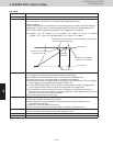
Example —