


2
2 - 11
W-2WAY ECO-i SYSTEM
Outdoor Unit Repair Procedures
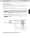
5. Recovering Refrigerant
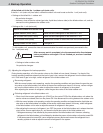
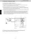
(2) If the remote controller (RCS-TM80BG) is not available for maintenance of the outdoor unit
Determine the outdoor unit where the unit No. setting (S007) (3P DIP switch) (Blue) on the outdoor unit
control PCB is set to No. 1.
Short-circuit the test-run pin (CN023) on the PCB to start test run operation.
Leave the unit running for a while, and touch the gas tubing with fingers to determine whether the unit is
running in cooling or heating mode.
If it is in heating, follow the step and later procedures.
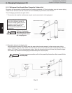
Release the short-circuit at the test-run pin (CN023) on the outdoor unit control PCB of the No. 1 unit. Then
short-circuit the stop pin (CN104) to stop operation.
Short-circuit the mode-change pin (CN101) on the outdoor unit control PCB of the No. 1 unit.
Switching of the 4-way valve occurs immediately before operation starts. Therefore it does not change at
this time. (Mode change cannot be judged from the sound.)
Short-circuit the test-run pin (CN023) on the PCB to start test run operation. Leave the unit running for a
while, and touch the gas tubing with fingers to determine that the unit is running in cooling mode.
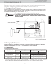
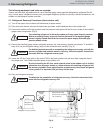
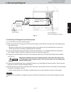
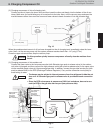
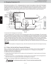
5-2-2. Refrigerant recovery procedures (1) (using indoor unit ball valve)
(1) If a ball valve with a service port has been provided in the indoor unit as shown in Fig. 10, follow the instructions
given in (2) through (6) below. If the service port is instead located in the outdoor side, follow the instructions in
“5-2-3. Refrigerant recovery procedures (2).”
(2) After running the unit in Cooling mode for about 5 minutes as described in “5-2-1. Cooling operation (for all
units),” fully close the liquid tube ball valve.
(3) Run the unit in Cooling mode for 10 to 20 minutes more.
(4) Fully close the gas tube ball valve, and stop the operation of all units.
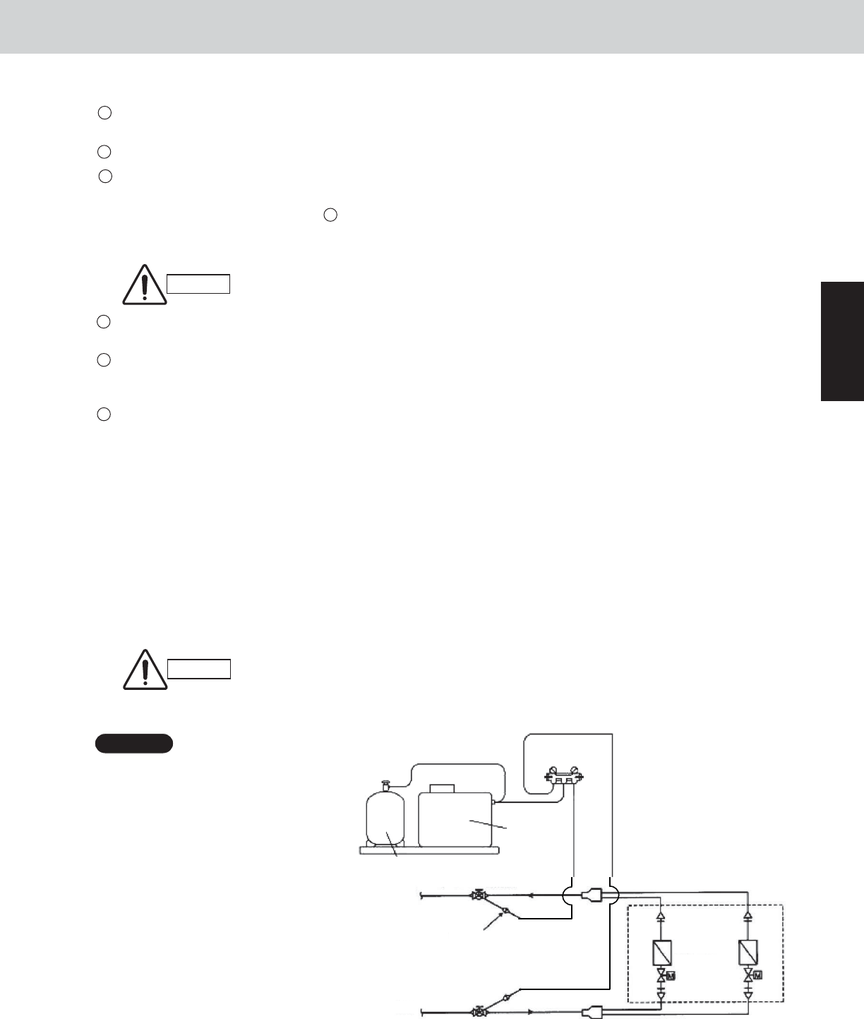
(5) Use hoses to connect the manifold gauge valves, refrigerant recovery unit, and refrigerant recovery cylinder
with each other. (Fig. 10)Do each connection quickly to prevent air from entering the tubing.
Remaining refrigerant may create internal pressure, therefore care should be
taken when connecting the hoses.
(6) Recover the remaining refrigerant from the indoor unit using the refrigerant recovery unit.
To determine completion of refrigerant
recovery, follow the instructions that
came with the refrigerant recovery unit.
CAUTION
NOTE
Hi
Manifold
gauge
Refrigerant recovery cylinder
Outdoor
unit
side
Gas tube
Liquid tube
Indoor unit
Refrigerant
recovery
unit
Service port
Ball valve (separately purchased)
Lo
1
2
3
4
5
6
Fig. 10
4
Cooling : low temperature (68 °F or lower)
Heating : high temperature (140 °F or higher)
The gas tubing becomes hot (140 °F or higher) in heating mode. Be careful so as
not to be burnt when touching the tubing.
*
CAUTION