


2
2 - 21
W-2WAY ECO-i SYSTEM
Outdoor Unit Repair Procedures
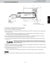
9. Pumping Out Refrigerant from Outdoor Unit
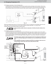
(8) Short-circuit the vacuum application pin on the outdoor unit control PCB of the unit to be repaired. Then turn ON
the outdoor unit power.
When the vacuum application pin is short-circuited and the power is turned ON, all
solenoid valves in the outdoor unit are forced open, allowing the refrigerant to be
recovered from all tubes which are separated by solenoid valves. If this work is not
performed, it will not be possible to recover all of the refrigerant at the refrigerant
recovery device. Be sure to perform this step.
Open both Hi- and Lo-side valves on the manifold gauge valves, and recover the refrigerant remaining in
the outdoor unit. After that, measure the amount of recovered refrigerant.
To determine the completion of refrigerant recovery, follow the instructions that came with the refrigerant recovery
unit.
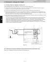
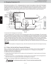
9-2. If Remote Controller is Not Available for maintenance of Outdoor Unit
(1) Refer to “4. Backup Operation” and perform backup operation.
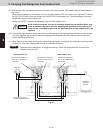
(2)
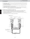
Connect the manifold gauge valves at the Lo side to the low-pressure outlet port of the outdoor unit to be
repaired. Also connect the refrigerant recovery cylinder to any one of the normal outdoor units at the liquid line
service port (Schrader-type push-to-release valve). Perform the connection work quickly so that no air is
allowed to enter. (Fig. 20)
* Connecting the refrigerant recovery cylinder is done to prevent pressure from rising excessively during the
backup operation by recovering the refrigerant from the outdoor unit to be repaired.
(Measure the weight of the refrigerant and cylinder itself beforehand and provide sufficient safety measures,
such as installing a high-pressure cutout in the circuit.)
The hoses may be subject to internal pressure from the refrigerant inside the out-
door unit. Check that the manifold gauge valves are fully closed beforehand.
A Schrader-type push-to-release valve is provided at each connection port.
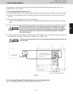
(3) Determine the outdoor unit where the unit No. setting (S007)(3P DIP switch)(BLU) on the outdoor unit control
PCB is set to No.1.
(4) Short-circuit the test-run pin (CN023) to start operation.
(5) Leave the unit running for a while, and then touch the gas tubing with fingers to determine whether the unit is
running in cooling or heating mode. If it is in heating, follow the step (6) and later procedures.
(6) When the unit is operating in heating mode, release the short-circuit at the test-run pin on the outdoor unit con-
trol PCB of the No. 1 unit. Then short-circuit the stop pin (CN104) to stop operation.
(7)
Short-circuit the mode-change pin (CN101) on the outdoor unit control PCB of the No. 1 unit.
Switching of the 4-way valve occurs immediately before operation starts. Therefore it does not change at this
time. (Mode change cannot be judged from the sound.)
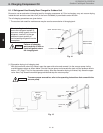
(8) Short-circuit the test-run pin (CN023) to start operation, leave the unit running for a while. Touch the gas tubing
with fingers to determine whether the unit is running in cooling.
NOTE
CAUTION
CAUTION
CAUTION
*
Cooling : low temperature (68 F or lower)
Heating : high temperature (140 F or higher)
The gas tubing becomes hot (140 F or higher) in heating mode. Be careful so as
not to be burnt when touching the tubing.