


2
2 - 31
W-2WAY ECO-i SYSTEM
Outdoor Unit Repair Procedures
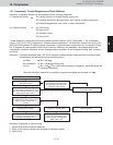
10. Compressor
Removal
(1)
(2) Follow the instructions in “1. Removing Panels” and “2. Removing Electrical Component Box and Duct” and
remove the corresponding parts from the outdoor unit where the compressor will be replaced.
(3)
(4)
(5)
(6)
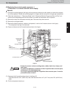
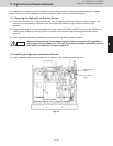
(7) Disconnect the 3 brazed locations shown in the figure 25.
(8)
CAUTION
Fig. 25
Crankcase heater
Bolt
Washer: 1
Rubber washer: 1
(1 each at the 3 locations)
Protect the oil
equalizer tube
connector
s
Front view (Type 96)
Remove
discharge sensor
Constant-speed
compressor
(left side)
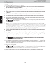
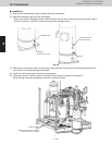
(B) Replacing the constant-speed compressor 1
(Compressor 2 on remote controller alarm display)
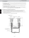
Connect the manifold gauge to the high- and low-pressure outlet ports at the outdoor unit where the compres-
sor will be replaced. Connect the manifold gauge to a nitrogen cylinder and perform nitrogen gas replacement.
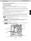
Remove the cap at the compressor terminal plate. Disconnect the power terminal.
Remove the crankcase heater.
Remove the bolts(3 locations), washers, and spacers (1 each at the 3 locations shown in the figure).
* The compressor rear leg is not anchored.
Prepare to disconnect the 3 brazed locations shown in the figure.
Brazed locations (3)
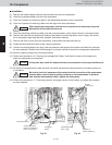
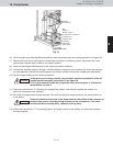
• Protect the sensors and surrounding plates, rubber, lead wires, clamps, and
other items.
Pay particular attention to protection of the oil equalizer tube connector parts,
and removal of the discharge sensor.
An O-ring is mounted inside the oil equalizer tube connector parts. It must be
protected and do not lose it.
* First disconnect the ø1/4" (ø6.35 mm) tube, then disconnect the ø1/2" (ø12.7 mm) and ø7/8" (ø22.22 mm)
tubes.
Pull the compressor toward you.