


R-22AT
R-24AT
12
3. CARRY OUT 4R CHECKS.
CAUTION: IF THE temperature fuse INDICATES AN OPEN CIRCUIT AT ROOM TEMPERATURE,
REPLACE temperature fuse.
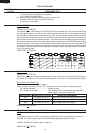
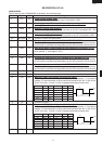
I THERMISTOR TH1, TH2, TH3 TEST
Open Close Display or
temperature temperature Condition Check point
Magnetron tem-
perature fuse (Up-
per)
TF1
Magnetron tem-
perature fuse
(Lower)
TF2
Exhaust tempera-
ture fuse
TF3
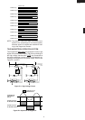
150˚C
120˚C
Non resetable
type
Non resetable
type
EE1
EE3
EE2
Oven shut
off
Magnetron
MG1 Failure:
Test magnetron
MG1 and Blower motor.
Magnetron MG1, MG2 Failure: Test magnetron MG1,
MG2. Check blower motor and ventilation opening.
Magnetron MG2 Failure:
Test magnetron
MG2 and Blower motor.
Food has been burned in oven.
Temperature of oven inside is very high.
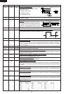
F WEAK POINT F3 TEST
CARRY OUT 3D CHECKS.
If the weak point F3 is blown, there could be a shorts or grounds in electrical parts or wire harness.
Check them and replace the defective parts or repair the wire harness.
CARRY OUT 4R CHECKS.
CAUTION: Only replace weak point F3 with the correct value replacement.
If incorrect readings are obtained, make the necessary switch adjustment or replace the switch.
CARRY OUT 4R CHECKS.
G FUSE F1, F2 F10A TEST
CARRY OUT 3D CHECKS.
If the fuse F1 F10A (or F2 F10A) is blown when the door is opened, check the interlock switch SW1
(or SW2) and monitor switch SW3 (or SW4).
If thefuse F1 F10A (or F2 F10A) is blown by incorrect door switching replace the defective switch(s)
and the fuse F1 F10A (or F2 F10A).
CARRY OUT 4R CHECKS.
CAUTION: Only replace fuse F1 F10A (or F2 F10A) with the correct value replacement.
H TEMPERATURE FUSE TF1, TF2, TF3 TEST
TEST PROCEDURES
PROCEDURE
LETTER COMPONENT TEST
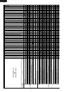
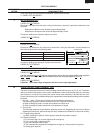
Table: Terminal Connection of Switch
Plunger Operation COM to NO COM to NC
Released Open circuit Short circuit
Depressed Short circuit Open circuit
COM; Common terminal,
NO; Normally open terminal
NC; Normally close terminal
1. CARRY OUT 3D CHECKS.
2. A continuity check across the temperature fuse terminals should indicate a closed circuit unless the
temperature of the temperature fuse reaches specfied temperature as shown below.
1. CARRY OUT 3D CHECKS.
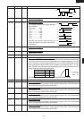
2. Follow the procedures below for each thermistor.
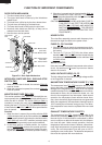
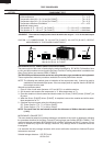
2-1. THERMISTOR TEST
Disconnect the connector of the thermistor from the switch harness. Measure the resistance of the
magnetron thermistor with an ohmmeter. Connect the ohmmeter leads to the leads of the thermistor.
Resistance: Approx. 500 kΩ -- 1 MΩ