


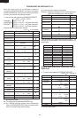

R-22AT
R-24AT
26
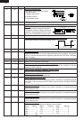
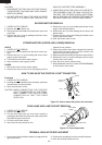
CAUTION:
1. DISCHARGE THE TWO HIGH VOLTAGE CAPACI-
TORS BEFORE TOUCHING ANY OVEN COMPO-
NENTS OR WIRING.
2. DO NOT REPLACE ONLY THE HIGH VOLTAGE
RECTIFIER. IF IT IS DEFECTIVE, REPLACE THE
HIGH VOLTAGE RECTIFIER ASSEMBLY.
3. WHEN REPLACING THE HIGH VOLTAGE RECTI-
FIER ASSEMBLY AND THE HIGH VOLTAGE CA-
PACITOR, THE CATHODE (EARTH) SIDE TERMI-
NAL OF THE HIGH VOLTAGE RECTIFIER MUST BE
SECURED FIRMLY WITH A EARTHING SCREW.
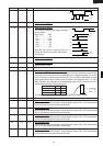
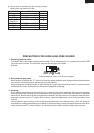
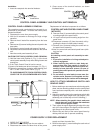
1. CARRY OUT
3D CHECKS.
2. Remove the rear cabinet, too.
3. Disconnect the wire leads from the blower motor and
noise filter.
4. Remove the one (1) screw holding the blower motor
angle to the oven cavity.
BLOWER MOTOR REMOVAL
5. Remove the one (1) screw holding the blower motor
angle to the chassis support.
6. Remove the one (1) screw holding the air duct to the
blower motor.
7. Remove the four (4) screws holding the blower motor
angle to the blower motor.
8. Now, the blower motor is free.
UPPER
1. CARRY OUT 3D CHECKS.
2. Disconnect the wire leads from the stirrer motor (up-
per).
3. Remove the one (1) screw holding the stirrer motor
(upper) to the oven cavity.
4. Turn and lift up the stirrer motor (upper).
5. Now, the stirrer motor (upper) is free.
LOWER
1. Disconnect oven from the power supply.
2. Remove the stirrer motor cover by snipping off the
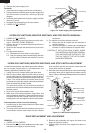
STIRRER MOTORS (UPPER AND LOWER) REMOVAL
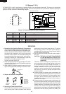
Procedure
1. CARRY OUT 3D CHECKS.
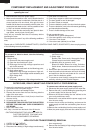
2. Pushing the lever of positive lock
®
connector, pull down
the connector from the terminal.
3. Now, the connector is free.
CAUTION: WHEN CONNECTING THE POSITIVE
LOCK
®
CONNECTORS TO THE TERMI-
NALS, CONNECT THE POSITIVE LOCK
®
CONNECTOR SO THAT THE LEVER
FACES YOU.
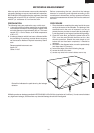
HOW TO RELEASE THE POSITIVE LOCK
®
CONNECTOR.
Figure C-2. How to release the positive lock connector.
material in four portions.
3. Where the portions have been snipped off bend the
portions flat. No sharp edge must be evident after
removal of the stirrer motor cover.
4. Disconnect the wire leads from the stirrer motor (lower).
5. Remove the one (1) screw holding the stirrer motor
(Lower) to the oven cavity.
6. Now, the stirrer motor (lower) is free.
7.
After replacement use one (1) screw (XOTWW40P08000)
to fit the stirrer motor cover.
Terminal
Push
Pull down
1
Lever
Positive lock®
connector
2
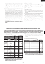
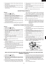
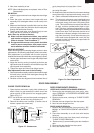
1. CARRY OUT 3D CHECKS.
2. Remove the oven lamp.
3. Pull the wire leads from the oven lamp socket by
pushing the terminal hole of the oven lamp socket with
the small flat type screw driver.
4. Lift up the oven lamp socket .
5. Now, the oven lamp socket is free.
OVEN LAMP AND LAMP SOCKET REMOVAL
Figure C-3. Oven lamp socket
Oven lamp
socket
Terminal
Wire lead
Terminal hole
Flat type small
screw driver
TERMINAL INSULATOR REPLACEMENT
1. Open covers of the terminal insulator by using small flat
type screw driver.
2. Remove the receptacle from the terminal insulator.
3. Now, the terminal insulator is free.