


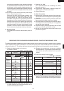

R-22AT
R-24AT
25
5. Pull out the wire lead(s) of high voltage transformer(s)
from the tube.
6. Disconnect wire lead(s) of high voltage transformer(s)
from high voltage capacitor(s).
7. Disconnect the high voltage fuse(s) from high voltage
transformer(s).
Removal
1. CARRY OUT
3D CHECKS.
2. Remove the rear cabinet, too.
3.
Remove the magnetron from the waveguide flange,
referring to "MAGNETRON(S) REMOVAL".
4. Now, the magnetron with the magnetron thermistor
should be free.
5. Remove the thermistor angle from the magnetron by
pulling out.
6. Straighten the tab of the magnetron thermistor angle
holding the magnetron thermistor.
7. Remove the magnetron thermistor from the thermistor
angle.
8. Now, the magnetron thermistor is free.
Re-install
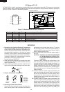
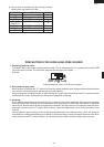
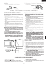
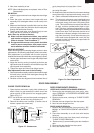
1. Install the magnetron thermistor to the thermistor angle
as shown in Figure C-1.
2. Hold the magnetron thermistor to the thermistor angle
by bending the tab of the thermistor angle.
3. Insert the thermistor angle between the 2nd. fin and
3rd. fin from the upper fin of the magnetron and push
it until the thermistor angle stops.
NOTE: The magnetron thermistor should be between the
upper fin and the 2nd. fin.
8. Disconnect the main wire harness from high voltage
transformer(s).
9. Remove two (2) screws holding each power trans-
former to base plate.
10.Remove the high voltage transformer(s) from base
plate.
12.Now, high voltage transformer(s) are free.
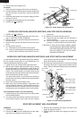
MAGNETRON(S) REMOVAL
Removal
1. CARRY OUT 3D CHECKS.
2. Remove the rear cabinet, too.
3. Remove the two (2) screws holding magnetron ex-
haust duct to upper and lower waveguide.
4. Remove the magnetron exhaust duct from oven cavity.
5. Disconnect wire leads from magnetron(s ).
6. Disconnect magnetron thermistor from the connector
of the stop switch harness.
7. Remove the one (1) screw holding the thermistor angle
to the upper magnetron.
8. Remove the four (4) screws holding each magnetron to
upper and/or lower waveguide. When removing the
screws, hold the magnetron to prevent it from falling.
9. Remove the magnetron(s) from upper and/or lower
waveguide with care so magnetron antenna is not hit
by any metal object around antenna.
10.Pull out the thermistor angle from the upper magnet-
ron.
11.Now, the magnetron(s) is (are) free.
CAUTION: WHEN REPLACING MAGNETRON, BE
SURE THE R.F. GASKET IS IN PLACE AND
MOUNTING SCREWS ARE TIGHTENED
SECURELY.
MAGNETRON THERMISTOR REPLACEMENT
4. Re-install the magnetron to the waveguide flange with
four (4) screws.
5. Re-install the thermistor angle to the waveguide flange
with one (1) screw.
6. Re-install the magnetron exhaust duct to the upper and
lower waveguide flanges with two (2) screws.
7. Route the thermistor harness under the magnetron
temperature fuse.
8. Connect the thermistor harness to the stop switch
harness.
9. Connect the wire leads to the upper magnetron, refer-
ring to the pictorial diagram.
10.Re-install the power supply cord, rear cabinet and
outer case cabinet to the oven by reversing the proce-
dures of "OUTER CASE, REAR CABINET AND
POWER SUPPLY CORD REMOVAL".
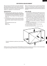
Figure C-1. Magnetron thermistor installation
1. CARRY OUT 3D CHECKS.
2. Remove the rear cabinet, too.
3. Remove two (2) screws holding earth side terminals of
high voltage rectifier assembly to the capacitor holder
and oven cavity.
4.
Disconnect all wire leads from the high voltage capacitor.
5. Disconnect high voltage fuse(s) from the high voltage
transformer(s). Now, high voltage fuse(s) is(are) free.
HIGH VOLTAGE CAPACITOR, HIGH VOLTAGE FUSE AND HIGH VOLTAGE RECTIFIER
ASSEMBLY REMOVAL
6.
Remove the three (3) screws holding the blower motor to
the top of oven cavity, the chassis support and air duct.
7. Disconnect high voltage wire lead(s) of the high volt-
age rectifier assembly from the magnetron(s).
Now, the the high voltage rectifier assembly is free.
8. Remove two (2) screws holding the capacitor holder to
oven cavity.
Now, the capacitors are free.
Upper magnetron
Upper fin
Tab
Thermistor
angle
Magnetron
thermistor