


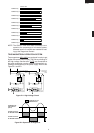

R-22AT
R-24AT
13
TEST PROCEDURES
PROCEDURE
LETTER COMPONENT TEST
If the meter does not indicate above resistance, replace the thermistor.
3. CARRY OUT
4R CHECKS.
J MOTOR WINDING TEST
CARRY OUT 3D CHECKS.
Disconnect the leads from the motor. Using an ohmmeter, check the resistance between the two
terminals.
Resistance of Blower motor should be approximately 60Ω.
Resistance of Antenna motor should be approximately 8.8 kΩ.
If incorrect readings are obtained, replace the motor.
CARRY OUT 4R CHECKS.
If incorrect readings are absorbed, replace the noise filter.
CARRY OUT 4R CHECKS.
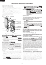
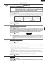
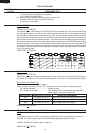
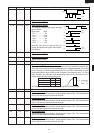
K NOISE FILTER TEST
CARRY OUT 3D CHECKS.
Disconnect the leads from the terminals of noise filter. Using an ohmmeter, check between the
terminals as described in the following table.
MEASURING POINT INDICATION OF OHMMETER
Between N and L Approx. 680 kΩ
Between terminal N and WHIT Short circuit
Between terminal L and BLK Short circuit
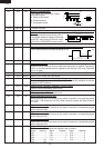
L HIGH VOLTAGE FUSE F4, F5 TEST
CARRY OUT 3D CHECKS.
If the high voltage fuse F4 (or F5) is blown, there could be a short in the high voltage rectifier or the magnetron
MG1 (or MG2). Check them and replace the defective parts and the high voltage fuse F4 (or F5).
CARRY OUT 4R CHECKS.
CAUTION: Only replace high voltage fuse with the correct value replacement.
F3 : WEAK POINT
NOISE FILTER
NOISE SUPPRESSION COIL
DISCHARGE RESISTOR 680 kΩ 1/2W
DISCHARGE RESISTOR 10 MΩ 1/2W
LINE CROSS CAPACITOR 0.22µF/ AC250V
LINE CROSS CAPACITOR
10000 pF/ AC250V
LINE CROSS CAPACITOR
10000 pF/ AC250V
L
BLK
WHT
N
M TOUCH CONTROL PANEL ASSEMBLY TEST
The touch control panel consists of circuits including semiconductors such as LSI, IC, etc. Therefore,
unlike conventional microwave ovens, proper maintenance cannot be performed with only a voltmeter
and ohmmeter. In this service manual, the touch control panel assembly is divided into two units,
Control Unit and Key Unit, troubleshooting by unit replacement is described according to the symptoms
indicated.
1. Key Unit Note : Check key unit ribbon connection before replacement.
The following symptoms indicate a defective key unit. Replace the key unit.
a) When touching the pads, a certain pad produces no signal at all.
b) When touching the pads, sometimes a pad produces no signal.
2. Control Unit
The following symptoms may indicate a defective control unit. Replacing the control unit. Before
replacing the control unit, perform the key unit test (Procedure N) to determine if control unit is faulty.
2-1 Programming problems.
a) When touching the pads, a certain group of pads do not produce a signal.
2-2 Display problems.
a) For a certain digit, all or some segments do not light up.
b) For a certain digit, brightness is low.
c) Only one indicator does not light.
d) The corresponding segments of all digits do not light up; or they continue to light up.
e) Wrong figure appears.