


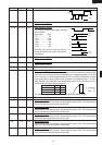

R-22AT
R-24AT
27
CONTROL PANEL ASSEMBLY REMOVAL
The complete control panel should be removed for re-
placement of components. To remove the control panel,
proceed as follows:
1. Disconnect the oven from power supply.
2. Wait for 60 seconds to discharge the high voltage
capacitor.
3. Remove the air intake filter assembly from the base
plate.
4. Remove two (2) screws holding the control panel to the
base plate.
5. Pull down the control panel and remove it forward.
6. Disconnect connectors and wire leads from the control
unit.
7. Now the control panel assembly is free.
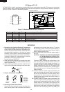
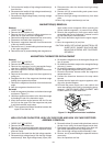
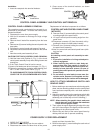
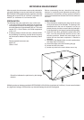
CAUTION FOR TOUCH CONTROL PANEL REMOVAL
1) Hold the lower end (Position A, Fig. 1) of the touch
control panel assembly firmly while sliding it down and
toward you.
2) If the Touch Control Panel is hard to remove;
(1) Insert a flat head screw driver into space B . (Fig. 1)
(2) Rotate the screwdriver clockwise while holding posi-
tion C of the Touch Control Panel. (Fig. 2)
TO AVOID DAMAGE TO TOUCH CONTROL PANEL,
COVER THE TIP OF SCREWDRIVER WITH TAPE.
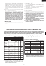
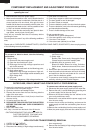
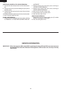
Installation
1. Insert the receptacle into terminal insulator.
2. Close covers of the terminal insulator, as shown
illustlated below.
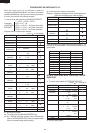
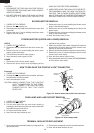
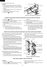
CONTROL PANEL ASSEMBLY AND CONTROL UNIT REMOVAL
Replacement of individual component is as follows:
CONTROL UNIT AND CONTROL PANEL FRAME
(WITH KEY)
8. Remove three (3) screws holding the control panel
mounting angle to the panel frame.
9. Lift up the control panel mounting angle from the
panel frame.
10.Disconnect connector (G) from the control unit by
pushing the hooks of cable holder inwardly.
11.Remove four (4) screws holding the control unit to
the panel frame assembly.
12.Now, the control unit and control panel frame (with
key) are free.
CAUTION:
At installing control panel unit assembly to main
body set:
1. Ensure the installation of wiring-related parts
without negligence.
2. When inserting key cable to main body set,
ensure them free from caught-in trouble. In
addition, when installing the control panel as-
sembly to base plate with screws, be sure of
pushing the control panel unit upward to fix with
screws firmly.
3. Do not allow any wire leads to come near the
varistor works, because it will explode and the
wire leads near by the varistor will be damaged.
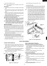
HOW TO ATTACH MEMBRANE SWITCH AND
GRAPHIC SHEET
1. Before attaching a new membrane switch and graphic
sheet, remove remaining adhesive on the control panel
frame surfaces completely with a soft cloth soaked in
alcohol.
2. Attach the graphic sheet to the membrane switch, with
adjusting their upper edges and right edges. (This
assembly part is called key unit in the following.)
NOTE : When attaching the graphic sheet, make sure
that air does not come between the membrane
switch and the graphic sheet.
3. Then, adjust the upper edge and right edge of the key
unit to the lower edge of the display window and the
right flange of the control panel frame.
4. Stick the key unit firmly to the control panel frame by
rubbing with soft cloth to prevent scratching.
POWER SUPPLY CORD REPLACEMENT
Flat type
screw driver
Terminal
insulator
RECEPTACLE
COVERS
B
A
C
B
Fig. 1
Fig. 2
TOUCH CONTROL PANEL
SCREW DRIVER
1. CARRY OUT 3D CHECKS
2. Release the cord bushing from the rear cabinet.
3. Disconnect the brown and blue wires of the power
supply cord from the noise filter.
4. Remove the single (1) screw holding the earth wire of
power supply cord.