


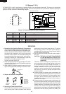

R-22AT
R-24AT
16
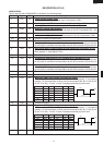
2. Key Unit
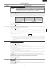
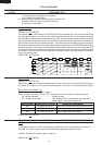
The key unit is composed of a matrix circuit in which
when a key it touched, one of signals P33 - P34
generated by the LSI, is passed through the key and
returned to the LSI as one of signals P24 - P27. This
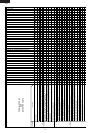
model has 20 Memory pads. When the oven is shipped,
Memory pad 1 to 10 are set as follows: fig.1.
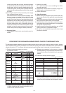
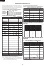
Memory No. Cook Time Output Power
1 5 sec. 100%
2 10 sec. 100%
3 20 sec. 100%
4 30 sec. 100%
5 40 sec. 100%
6 50 sec. 100%
7 1 min. 100%
81 min. 15 sec. 100%
91 min.30 sec. 100%
02 mins. 100%
(fig. 1)
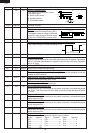
This model has a double quantity pad. When the oven
is shipped, Magnification "1.8" is preset in the double
quantity pad. This model has an defrost pad. When the
oven is shipped, defrost is set as follows: fig.2.
1STAGE 2STAGE 3STAGE
POWER 40% 30% 20%
DEFROSTING TIME 0.2T+20sec 0.13T+30sec. 0.67T-50sec.
(fig. 2)
NOTE :
"CHECK" indicator will flash at half of defrosting time.
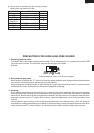
TOUCH CONTROL PANEL ASSEMBLY
OUTLINE OF TOUCH CONTROL PANEL
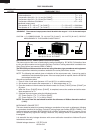
The touch control section consists of the following units as
shown in the touch control panel circuit.
(1) Control Unit
(2) Key Unit
The principal functions of these units and the signals
communicated among them are explained below.
1. Control Unit
Signal of key touch and oven function control are all
processed by one microcomputer.
1) Power Supply Circuit
This circuit changes output voltage at the secondary
side of the touch control transformer to voltages re-
quired at each part by full wave rectifying circuit,
constant voltage circuit, etc..
2) Reset Circuit
This is an Auto-clear Circuit, i.e., a reset circuit, which
enables IC1 to be activated from initial state.
3) Power Synchronizing Signal Generating Circuit
This is a circuit for generating power synchronizing
signal by virtue of the secondary side output of touch
control transformer.
This signal is used for a basic frequency to time
processing and so on.
4) Clock Circuit
This is a circuit for controlling clock frequency required
for operating I-1.
5) I-1 (Main Processor)
This is a one-chip microcomputer, responsible for
controlling the entire control unit.
6) I-2 (Memory Processor)
This is a memory IC, responsible for memory function.
7) Display Circuit
This is a circuit for driving display tubes by I-1 output.
8) Key Input Circuit
This is a circuit for transmitting key input information to
I-1.
9) Sound-body Driving Circuit
This is a circuit for driving sound body by I-1 output.
10) Relay Driving Circuit
This is a circuit for driving output relay by I-1 output.
11) Stop Switch Circuit
This is a circuit for driving I-1 to detect door opening/
closing.
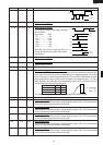
12) Exhaust Air Temperature Detecting Circuit
This is a circuit for transmitting output change of
thermistor (Exhaust thermistor) to I-1.
13) Magnetron Temperature Circuit.
(Detect Noload or Fan Lock)
This is a circuit for transmitting output change of
thermistor (Magnetron thermistor) to I-1.