


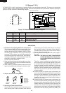

R-22AT
R-24AT
20
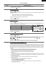
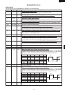
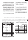
2-2 Memory IC (I-2)
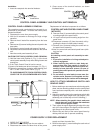
CAT24WC16PI is a 4K-bit, serial memory, enabling CMOS to be erased/written electrically. This memory is constructed
with 512 registers x 8bits, enabling individual access, read and write operations to be performed. Details of input/output
signal for IC2 are as shown in the following diagram.
Figure T-2. Relation between Pin Nos, and Signals
Pin No. Signal I/O Description
1-3 A0-A2 IN Connected to GND.
4 VSS IN Connected to VC(-5V).
5 SDA IN/OUT Serial data input/output : input/outputs data to I-1.
6 SCL IN Clock signal input : input/outputs serial data at every one pulse.
7 TEST IN Connected to VC(-5V).
8 VCC IN Connected to GND.
SERVICING
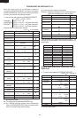
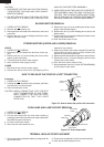
Transistor
KIA79L05P
DTB143ES
DTD143ES
KRA101M
Transistor
2SB1238
Transistor
2SB953
approx. 1M ohm
3
2
1
E
C
B
E
C
B
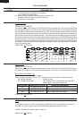
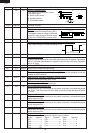
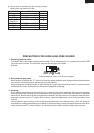
FUNCTIONAL DIAGRAM
E PROM
512 x 8
2
START
STOP
LOGIC
CONTROL
LOGIC
SLAVE ADDRESS
REGISTER
COMPARATOR
H.V. GENERATION
TIMING
& CONTROL
64
YDEC
8
DATA REGISTER
Dout
CK
3
1
5
64
XDEC
START CYCLE
INC
LOAD
WORD
ADDRESS
COUNTER
R/W
PIN
Dout
ACK
(6) SCL
(5) SDA
(4) Vss
(3) Vcc
A0
81
72
63
54
A1
A2
VSS
VCC
TEST
SCL
SDA
TOP VIEW
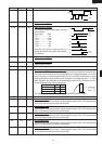
1. Precautions for Handling Electronic Components
This unit uses CMOS LSI in the integral part of the
circuits. When handling these parts, the following pre-
cautions should be strictly followed. CMOS LSI have
extremely high impedance at its input and output
terminals. For this reason, it is easily influenced by the
surrounding high voltage power source, static electric-
ity charge in clothes, etc, and sometimes it is not fully
protected by the built-in protection circuit.
In order to protect CMOS LSI.
1) When storing and transporting, thoroughly wrap them
in aluminium foil. Also wrap all PW boards containing
them in aluminium foil.
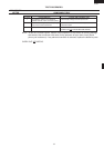
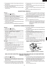
2) When soldering, ground the technician as shown in the
figure and use grounded soldering iron and work table.
2. Shapes of Electronic Components
3. Servicing of Touch Control Panel
We describe the procedures to permit servicing of the
touch control panel of the microwave oven and the
precautions you must take when doing so. To perform
the servicing, power to the touch control panel is
available either from the power line of the oven itself or
from an external power source.
(1) Servicing the touch control panel with power supply of
the oven:
CAUTION: THE HIGH VOLTAGE TRANSFORMER
OF THE MICROWAVE OVEN IS STILL
LIVE DURING SERVICING PRESENTS
A HAZARD.
Therefore, when checking the performance of the
touch control panel, put the outer cabinet on the oven
to avoid touching the high voltage transformer, or
unplug the primary terminal (connector) of the high
voltage transformer to turn it off; the end of such
connector must be insulated with an insulating tape.
After servicing, be sure to replace the leads to their
original locations.
A. On some models, the power supply cord between the
touch control panel and the oven itself is so short that
the two can’t be separated. For those models, check
and repair all the controls (sensor-related ones in-
cluded) of the touch control panel while keeping it
connected to the oven.
B. On some models, the power supply cord between the
touch control panel and the oven proper is long enough
that they may be separated from each other. For those
models, therefore, it is possible to check and repair the
controls of the touch control panel while keeping it
apart from the oven proper; in this case you must short
both ends of the door sensing switch (on PWB) of the