


R-22AT
R-24AT
19
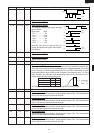
Pin No. Signal I/O Description
41-46 P17-P12 OUT Segment data signal.
Signal similar to P23..
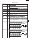
47-48 P11-P10 OUT Digit selection signal.
The relation between digit signal and digit
are as follows:
Digit signal Digit
P11.................... 1st.
P10................... 2nd.
P07....................3rd.
P06.................... 4th.
P05.................... 5th.
P04.................... 6th.
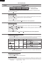
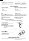
Normally, one pulse is output in every ß
period, and input to the grid of the Fluores-
cent Display.
49-52 P07-P04 OUT Digit selection signal.
Signal similar to P11.
53-55 P03-P01 OUT Segment data signal.
Signal similar to P23.
56 P00 - Terminal not used.
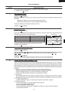
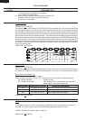
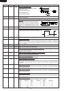
57-58 P37-P36 OUT (Sound) Voltage level control terminal.
This terminal (P37) is to control volume level of buzzer sound with terminals P36.
Since the volume level of buzzer sound depends on voltage energized, it is control
level in 3 steps by combining signal levels for P37 and P36. Relationship of signal
level combination to sound volume level is shown in the following table, 1~3 in the
table, however, are indicated in the descending order from the maximum level of
sound volume through the minimum level.
Sound Volume P36 P37
1, (Max.) L L
2, H L
3, (Min.) L H
*At Output terminal P47, rectangular wave signal of 2.5kHz is output.
59 P35 - Terminal not used.
60 P34 OUT Key strobe signal.
Signal applied to touch-key section. A pulse signal is input to P24 - P27 terminal while
one of G-4 line keys on key matrix is touched.
61 P33 OUT Key strobe signal.
Signal applied to touch-key section. A pulse signal is input to P24 - P27 terminal while
one of G-5 line keys on key matrix is touched.
62 P32 OUT Key strobe signal.
Signal applied to touch-key section. A pulse signal is input to P24 - P27 terminal while
one of G-6 line keys on key matrix is touched.
63 P31 OUT Key strobe signal.
Signal applied to touch-key section. A pulse signal is input to P24 - P27 terminal while
one of G-7 line keys on key matrix is touched.
64 P30 OUT Key strobe signal.
Signal applied to touch-key section. A pulse signal is input to P24 - P27 terminal while
one of G-8 line keys on key matrix is touched.
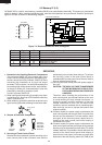
GND
-31(V)
§(50Hz)
H
L
GND
§(50Hz)
P11
P10
P07
P06
P05
P04
GND
-31(V)
-31(V)
A
A : 1,(Max) 20V
2, 13V
3,(Min) 7V