


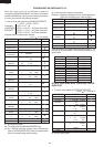

R-22AT
R-24AT
18
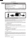
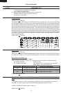
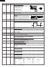
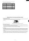
19 P47 OUT Signal to sound buzzer.
This signal is to control the 2.5kHz
continuous signal.
A: Switch touch sound.
B: Guidance sound.
C: Completion sound.
20-21 P46-P45 - Terminal not used.
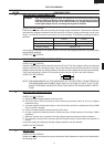
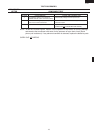
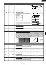
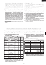
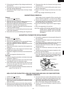
22 P44 OUT Oven lamp, Blower motor and Antenna motor driving signal (Square Waveform
: 50Hz).
To turn on and off the shut-off relay (RY1).
The Square waveform voltage is delivered
to the RY1 relay driving circuit and relays
(RY3, RY4, COOK RELAY) control circuit.
23-24 P43-P42 - Terminal not used.
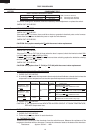
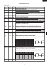
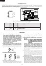
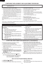
25 INT1 IN Signal synchronized with commercial power source frequency.
This is basic timing for all time processing of LSI.
26 INT0 IN Connected to VC(-5) through pull-down resistor.
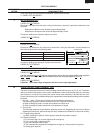
27 RESET IN Auto clear terminal.
Signal is input to reset the LSI to the initial state when power is supplied. Temporarily
set to "L" level the moment power is supplied, at this time the LSI is reset. Thereafter
set at "H" level.
28 P71 OUT Memory (EEPROM) clock output.
29 P70 IN/OUT Memory (EEPROM) data input/output.
30 XIN IN Internal clock oscillation frequency setting input.
The internal clock frequency is set by inserting the ceramic filter oscillation circuit with
respect to XOUT terminal.
31 XOUT OUT Internal clock oscillation frequency control output.
Output to control oscillation input of XIN.
32 VSS IN Power source voltage: -5V.
VC voltage of power source circuit input.
33 P27 IN Signal coming from touch key.
When either one of G-12 line keys on key matrix is touched, a corresponding signal
out of P30 - P34 will be input into P27. When no key is touched, the signal is held at
"L" level.
34 P26 IN Signal similar to P27.
When either one of G-11 line keys on key matrix is touched, a corresponding signal
will be input into P26.
35 P25 IN Signal similar to P27.
When either one of G-10 line keys on key matrix is touched, a corresponding signal
will be input into P25.
36 P24 IN Signal similar to P27.
When either one of G-9 line keys on key matrix is touched, a corresponding signal
will be input into P24.
37-40 P23-P20 OUT Segment data signal.
The relation between signals and indicators are as follows:
Signal Segment Signal Segment Signal Segment
P01..................... k P21 .........................h P15 ..................... d
P02...................... j P20 .........................g P14 ......................c
P03...................... i P17 .........................f P13 ..................... b
P23.................. LB P16 .........................e P12 ..................... a
P22..................UB
Pin No. Signal I/O Description
A
B
C
0.12 sec
2.4 sec
1.2 sec
1.2 sec
GND
-5V
T
200 sec.
200 sec.
H
L
20 msec
During cooking
GND
-5V
20 msec.
OFF
ON