


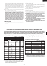
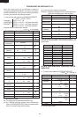

R-22AT
R-24AT
29
cavity face plate is to be less than 1.0mm.
3. The door is positioned with its face depressed toward
the cavity face plate.
4. Re-install outer case and check for microwave leakage
around door with an approved microwave survey me-
ter. (Refer to Microwave Measurement Procedure.)
Note: The door on a microwave oven is designed to act
as an electronic seal preventing the leakage of
microwave energy from oven cavity during cook
cycle. This function does not require that door be
air-tight, moisture (condensation)-tight or light-
tight. Therefore, occasional appearance of mois-
ture, light or sensing of gentle warm air movement
around oven door is not abnormal and do not of
themselves, indicate a leakage of microwave en-
ergy from oven cavity. If such were the case, your
oven could not be equipped with a vent, the very
purpose of which is to exhaust the vapor-laden air
from the oven cavity.
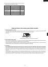
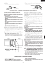
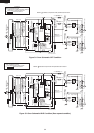
CHOKE COVER REMOVAL
1. Open the door and insert a putty knife (thickness of
about 0.5mm) in gap between the choke cover and
corner portion of door panel to free engaging parts.
Refer to Fig. C-7.
NOTE: As the choke cover and door panel are engage at
16 places, do not force any perticular part.
2. Remove the choke cover carefully. (If choke cover is
broken, replace with a new one.)
5. Now, door assembly is free.
NOTE: When individual parts are replaced, refer to "Door
Disassembly".
RE-INSTALL
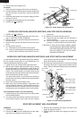
1. Insert the upper and lower oven hinges into door hinge
pins.
2. Insert the upper and lower oven hinges with door
assembly into rectangular holes of oven cavity front
plate.
3. Make sure that the door is parallel with oven face lines
(left and upper side line) and door latch heads pass
through the latch holes correctly.
4. Fasten upper and lower oven hinges firmly to oven
cavity with two (2) screws on each hinge.
Note: After any service to the door;
(A) Make sure that interlock switches, stop switch
and monitor switches are operating properly.
(Refer to chapter "Test Procedures".).
(B) An approved microwave survey meter should be
used to assure compliance with proper micro-
wave radiation emission limitation standards.
DOOR ADJUSTMENT
When removing and/or loosening hinges such as in door
replacement, the following adjustment criteria are taken.
Door adjustment is performed with the door properly
installed and closed and while the oven hinges are loose.
1. Loosen upper and lower oven hinges with phillips head
screw driver.
2. Adjust the door by moving it vertically so that the top
right hand corner of the door is in line with the top of the
control panel frame assembly.
3. Tighten the upper and lower oven hinge screws.
After adjustment, make sure of the following:
1. Door latch heads smoothly catch the latch hook through
the latch holes, and the latch head goes through the
center of the latch hole.
2. Deviation of the door alignment from horizontal line of
DOOR DISASSEMBLY
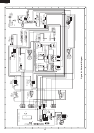
Figure C-7. Choke cover
DOOR COMPONENTS REMOVAL
UPPER AND LOWER OVEN HINGES REMOVAL
1. Remove the door assembly from oven cavity, refer-
ring to "REMOVAL" of "DOOR REPLACEMENT AND
ADJUSTMENT".
2. Remove choke cover, referring to "CHOKE COVER
REMOVAL".
3. Release the oven hinges from the door panel.
4. Now, the oven hinges are free.
DOOR HANDLE REMOVAL
1. Remove the door assembly from oven cavity, "RE-
MOVAL" of "DOOR REPLACEMENT AND ADJUST-
MENT".
2. Place door assembly on a soft cloth with latches
facing up.
3. Remove choke cover from door panel, referring to
"CHOKE COVER REMOVAL".
4. Remove two (2) screws holding the door handle to
door.
5. Remove the door handle from door panel.
6. Now, door handle is free.
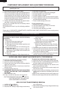
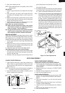
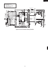
Figure C-6. Door Replacement
OUTER CASE
CABINET
UPPER
OVEN HINGE
LOWER
OVEN HINGE
LATCH
HEADS
UPPER
OVEN HINGE
LOWER
OVEN HINGE
CHOKE COVER
DOOR
HANDLE
LATCH HEAD
BENT
2
1
PUTTY KNIFE
PUTTY KNIFE
CHOKE COVER
DOOR PANEL
FRONT
BENT