


R-22AT
R-24AT
28
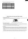
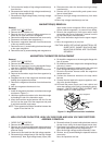
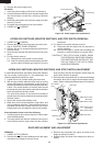
Figure C-4. Power supply cord replacement
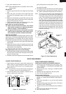
1. CARRY OUT 3D CHECKS.
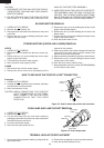
2. Remove the control panel from the oven cavity refer-
ring to “CONTROL PANEL REMOVAL”.
3. Remove the two (2) screws holding the latch hook to
the oven cavity.
4. Open the door and pull the latch hook out of the oven
cavity.
5. For stop switch removal
5-1. Disconnect the wire leads from the switch.
5-2. Push the retaining tabs outward slightly and then
pull the switch forwards and remove it from the
INTERLOCK SWITCHES, MONITOR SWITCHES, AND STOP SWITCH REMOVAL
latch hook.
6. For interlock or monitor switches removal
6-1. Disconnect the wire leads from the interlock or
monitor switches.
6-2. Remove the single (1) screw and nut holding the
interlock or monitor switches to the latch hook.
CAUTION: IF THE LATCH HOOK IS NEW, WHEN
THE INTERLOCK SWITCHES OR MONI-
TOR SWITCHES ARE INSTALLED, THE
TWO (2) TABS OF THE LATCH HOOK
SHOULD BE BROKEN.
5. Remove the power supply cord.
Re-install
1. Insert the power supply cord into the cord bushing.
2. Connect the brown and blue wires of power supply cord
into the terminals of noise filter, referring to pictorial
diagram.
3. Install the green/yellow wire of power supply cord with
the one (1) screw.
4. Re-install the cord bushing to the rear cabinet.
5. CARRY OUT 4R CHECKS.
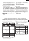
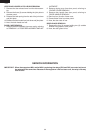
In case interlock switches, stop switch and monitor switches
do not operate properly due to a mis-adjustment, the
following adjustment should be made.
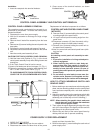
1. Loosen the two (2) screws holding the latch hook.
2. With the door closed, adjust the latch hook by moving
it back and forward, or up and down. In and out play of
the door allowed by the latch hook should be less than
0.5mm. The vertical position of the latch hook should
be placed where the stop switch and interlock switches
have activated with the door closed.
The horizontal position of the latch hook should be
placed where the monitor switches have activated with
the door closed.
3. Secure the screws with washers firmly.
4. Make sure of the interlock switches, stop switch, and
monitor switches operation. If those switches have not
activated with the door closed, loose two (2) screws
holding latch hook and adjust the latch hook position.
After adjustment, make sure of the following:
1. In and out play of door remains less than 0.5mm when
in the latched position.
2. The stop switch and interlock switches interrupt the
circuit before the door open when the door release
INTERLOCK SWITCHES, MONITOR SWITCHES, AND STOP SWITCH ADJUSTMENT
lever is pulled, and then and monitor switch close the
circuit when the door is opened.
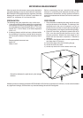
3. Re-install outer case and check for microwave leakage
around the door with an approved microwave survey
meter. (Refer to Microwave Measurement Procedure.)
Figure C-5 Latch Switch Adjustments
DOOR REPLACEMENT AND ADJUSTMENT
REMOVAL
1. CARRY OUT 3D CHECKS.
2. Remove the two (2) screws holding each of the upper
and lower oven hinges to the oven cavity.
3. Remove door assembly with upper and lower oven
hinges by pulling it forward.
4. Release upper and lower oven hinges from door as-
sembly.
Power supply cord
Cord bushing
Screw
Green/Yellow
wire
Brown wire
Blue wire
L
N
Noise filter
Latch head
SW4: Monitor switch
(Oven side)
SW3: Monitor switch
Latch hook
SW1: Interlock switch
SW2: Interlock switch
(Oven side)
SW5: Stop switch
Latch head
Joint lever
Door release
lever
Head lever