


R-22AT
R-24AT
14
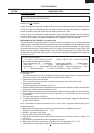
P PROCEDURES TO BE TAKEN WHEN THE FUSE ON THE PRINTED WIRING BOARD(PWB) IS
OPEN
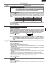
TEST PROCEDURES
PROCEDURE
LETTER COMPONENT TEST
f) A certain group of indicators do not light up.
g) The figure of all digits flicker.
2-3 Other possible problems caused by defective control unit.
a) Buzzer does not sound or continues to sound.
b) Cooking is not possible.
CARRY OUT
3D CHECKS.
If the display fails to clear when the STOP/CLEAR pad is depressed, first verify the flat ribbon cable
is making good contact, verify that the stop switch operates properly; that is the contacts are closed
when the door is closed and open when the door is open. If the stop switch is good, disconnect the flat
ribbon cable that connects the key unit to the control unit and make sure the stop switch is closed (either
close the door or short the stop switch connector ). Use the key unit matrix indicated on the control panel
schematic and place a jumper wire between the pins that correspond to the STOP/CLEAR pad making
momentary contact. If the control unit responds by clearing with a beep, the key unit is faulty and must
be replaced. If the control unit does not respond, it is faulty and must be replaced. If a specific pad does
not respond, the above method may be used (after clearing the control unit ) to determine if the control
unit or key pad is at fault.
CARRY OUT 4R CHECKS.
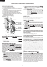
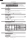
N KEY UNIT TEST
O RELAY TEST
CARRY OUT 3D CHECKS.
Remove the outer case and check voltage between Pin Nos. 3 and 5 of the connector (A) on the control
unit with an A.C. voltmeter. The meter should indicate 230 - 240 volts, if not check control unit circuity.
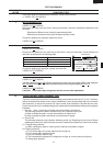
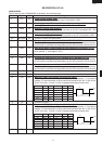
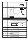
RY1, RY3 and RY4 Relay Test
These relays are operated by D.C. voltage.
Check voltage at the relay coil with a D.C. voltmeter during the microwave cooking operation.
DC. voltage indicated .............................Defective relay.
DC. voltage not indicated .......................Check diode which is connected to the relay coil. If
diode is good, control unit is defective.
RELAY SYMBOL OPERATIONAL VOLTAGE CONNECTED COMPONENTS
RY1 APPROX. 25.9V D.C. Oven lamp, Blower motor and Antenna motors
RY3 APPROX. 25.0V D.C. High voltage transformer (MG1)
RY4 APPROX. 25.0V D.C. High voltage transformer (MG2)
CARRY OUT 4R CHECKS.
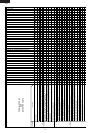
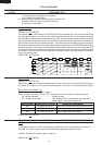
G9
G10
G11
G12
G1
1
2
3
4
5
6
7
8
9
0
G2 G3 G4 G5 G6 G7 G8
18
19
20
15
16
13
14
11
12
17
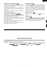
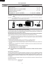
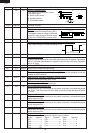
To protect the electronic circuits, this model is provided with a fine fuse added to the primary on
the PWB. If the fuse is open, follow the troubleshooting guide given below for repair.
Problem: POWER ON, indicator does not light up.
CARRY OUT 3D CHECKS.