


21
CTV-PRC007-EN
System
Options
Auxiliary
Condenser (Cont.)
Controls
The auxiliary condenser was designed
for simplicity of operation. Machine load,
water flow rate, and temperature
determine the amount of heat recovered.
There are no controls needed for heating
water temperature because no attempt
is made to maintain a specific hot water
temperature in or out of the auxiliary
condenser.
Operation
The auxiliary condenser is a factory-
mounted, separate, shell and tube heat
exchanger available on water-cooled
CenTraVac chillers.
Because hot refrigerant gas always
migrates to the area of lowest
temperature, auxiliary condenser
operation is simple. As hot gas leaves
the compressor, it is free to flow to the
auxiliary condenser or the standard
condenser. Since water entering the
auxiliary condenser is normally colder
than that entering the standard
condenser, the auxiliary condenser will
have a lower bundle temperature and
will attract the refrigerant gas. The
auxiliary condenser will recover as much
heat as the machine cooling load,
heating water temperature, and flow rate
will allow. All remaining heat will
automatically be rejected through the
standard condenser to the atmosphere
through the cooling tower. No controls
are needed to balance heat rejection in
the two condensers.
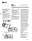
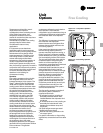
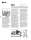
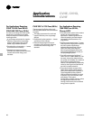
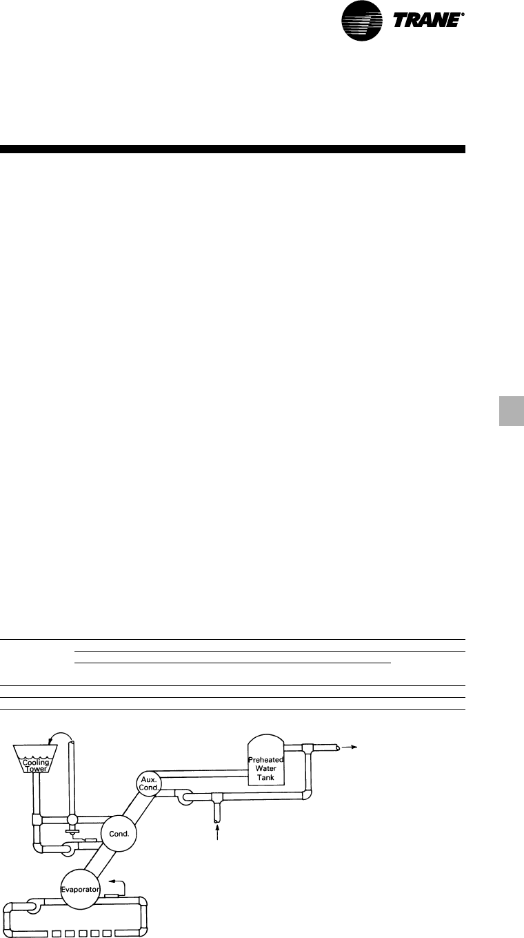
Good system design will include a
heated water bypass to ensure that
water does not circulate through the
auxiliary condenser when the chiller is
de-energized. There are several ways to
bypass the auxiliary condenser. When
the hot water system is installed as
shown in the figure below, the bypass is
automatic if the heating water pump is
interlocked with the chiller compressor
motor.
Another bypass arrangement is to install
a diverting valve. When interlocked with
the compressor motor, this valve diverts
the heating water flow to the
conventional heating system whenever
the chiller is not operating. These are
only examples of the many ways of
accomplishing a bypass.
Contact your local Trane sales office for
further specific information.
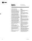
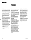
Table O-1 — Auxiliary Condenser Flow Limits and Connection Sizes
Auxiliary Two Pass
Condenser Inter Enhanced Smooth Bore Connection
Bundle Minimum Maximum Minimum Maximum Size
Size Gpm Gpm Gpm Gpm (In)
Standard 74 276 70 258 5
Large 121 453 115 423 5