


37
CTV-PRC007-EN
Controls
Sequence of Operation
For this sequence of operation it will be
assumed that the control source has
signaled the chiller to be in Automatic
(i.e. when there is a load present, the
chiller will turn on and when the load
disappears, the chiller will turn off). It is
also assumed that no diagnostic has
occurred either prior to start-up or during
run time and that no “special”
applications exist.
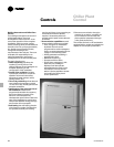
Modules
Conventional “relay logic” circuits have,
been replaced by software and hardware
imbedded in the CenTraVac
™
microprocessor controller. The functions
of the microprocessor are divided into
six standard modules. Optional modules
are available for those applications that
require additional control capability.
Optional communication interface
modules are available for alternative
control sources. All modules
communicate with each other on the
interprocessor communication bus (IPC).
All information is available and all
setpoint/setup adjustments can be
accomplished at the operator interface.
An optional remote display permits the
operator to monitor and operate the
chiller from a remote location.
The six standard modules consist of a
chiller module, a circuit module, a starter
module, a stepper module, a purge
module and local display module.
The chiller module is the master of the
chiller. It communicates commands to
other modules and collects data/status/
diagnostic information from other
modules over the IPC. The chiller
module performs the leaving evaporator
fluid temperature and limit control
algorithms arbitrating capacity against
any operating limit the chiller may find
itself working against.
The circuit module is assigned inputs
and outputs associated with the
refrigerant and lubrication circuits.
The starter module provides control of
the starter when starting, running and
stopping the motor. It provides interface
to and control of wye-delta, across the
line, primary reactor, auto transformer,
solid-state starters and Trane Adaptive
Frequency
™
drive. The starter module
also provides protection to both the
motor and the compressor in the form of
running overload, phase reversal, phase
loss, phase unbalance, momentary
power loss and compressor surge. All
diagnostics are communicated across
the IPC to the human interface.
The stepper module is designed to drive
the stepper motor inlet guide vane
actuator and other flow control devices
within a system. This module receives
from the chiller module the direction and
distance to drive the inlet guide vanes
and then generates the appropriate
signals to operate the stepper motor.
The purge module provides control of
the purge including all the inputs and
outputs to control the purge, to optimize
both purge and chiller efficiency, and to
communicate purge diagnostics to the
human interface.
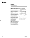
Before anything can begin, 115 volt
(50 or 60 Hz) power is applied to the
control panel. In that several control
source devices may coexist, the operator
determines which device has priority via
the operator interface. All control settings
at that control source are then in effect
(i.e. active setpoints). A control source is
the device that determines setpoints and
whether the chiller is auto/off (such as
local control panel, remote control
display, 4-20 mA external device, Tracer
™
,
generic BAS).
Power Off
Power On
Auto “Automatically Ready to Start
Evaporator Pump On Waiting for Need to Cool”
In Parallel: Restart Inhibit “Restart Temporarily Prevented -
Prelubrication Time Remaining [ : ]”
Condenser Flow Established “Establishing Condenser Flow
Start and Oil Pressure”
Run: Normal “Starting Compressor”
“Running Normal” or
Softloading “Softloading” or
Evaporator Limit “Running - Capacity Limited by
Condenser Limit Low Evaporator Temperature” or
Current/Demand Limit “Running - Capacity Limited by
Unload High Condenser Pressure”
“Machine is Preparing to Shutdown”
Stop “Operator Initiated Stop -
In Parallel: Close Inlet Guide Vanes Press Auto to Restart”
Run Compressor “Post Lubricating -
Post Lube Time Remaining [ : ]
Auto “Automatically Read to Start -
Waiting for Need to Cool”
Modules/Sequence
of Operation