TurboChef Technologies, Inc. C Series
8-2
CATALYTIC CONVERTER
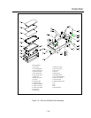
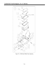
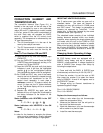
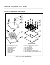
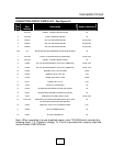
The catalytic converter (See Figure 8-1) is installed
in the return air duct behind the heater assembly.
The installation of the catalytic converter requires
a catalytic converter inner frame to properly
position it in the air path.
Due to the nature of most foods and the physics
governing the operation of the C3 SERIES oven,
grease buildup downstream of the cooking
chamber is inevitable. Strict cleaning regiments
can solve a majority of the problems, however,
recirculation of undiluted greasy saturated air is
the main cause of downstream grease
accumulation and any associated residual flavors.
The airborne grease tends to collect and bake
onto the oven surface downstream of the cooking
chamber. This grease, due to the high operating
temperatures of the oven, will start to rapidly
decompose into derivative organic compounds.
These decompositional derivatives generally have
positive and negative effects on cooking; the
shorter chain derivatives add favorable flavor
characteristics to the food, while the higher order
carbon chains lend unpleasant flavor char-
acteristics, such as bitter tarry tastes.
The installation of the catalytic converter greatly
effects the grease handling and any residual
flavors which might build up over time. A properly
operating catalytic converter causes the
conversion of airborne grease into water, carbon
dioxide and small amounts of nitrogen and
oxygen. The catalytic converter acts as a
combustion chamber for the airborne grease. The
catalysts present on the filter lowers the ignition
temperature of the airborne grease from
approximately 700ºF (371ºC) to 450–550ºF (232–
288ºC), allowing combustion to occur. The
operating temperature of the oven directly
determines the percentage of airborne grease
conversion. A single pass of the air stream yields a
20–30% improvement in air quality.
A problem with the catalytic converter is indicated
by a decrease in the effectiveness of browning
(caused by a reduction in airflow) or by flavor
transfer from one food group to another.
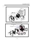
If you suspect the catalytic converter needs
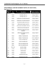
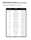
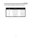
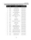
cleaning refer to figures on page 8-5 and below.
These diagrams provide you with a location
reference and exploded view (Note: The Return
Air Duct Assembly Panel and the Terminal Heat
Shield may be inverted on some C3/AB units. All
C3/C units will have this assembly inverted). It is
important to carefully remove the insulation and
replace it neatly. The metal foil helps shield
microwave emissions.
IMPORTANT NOTE:
The catalytic converter can be cleaned with
TurboCare® oven cleaner and thoroughly rinsed
with DISTILLED water. Let the catalytic converter
air dry before reinstalling. IF TurboCare oven
cleaner is not available DO NOT SUBSTITUTE-
USE DISTILLED WATER.


