


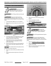
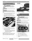
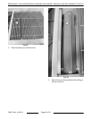
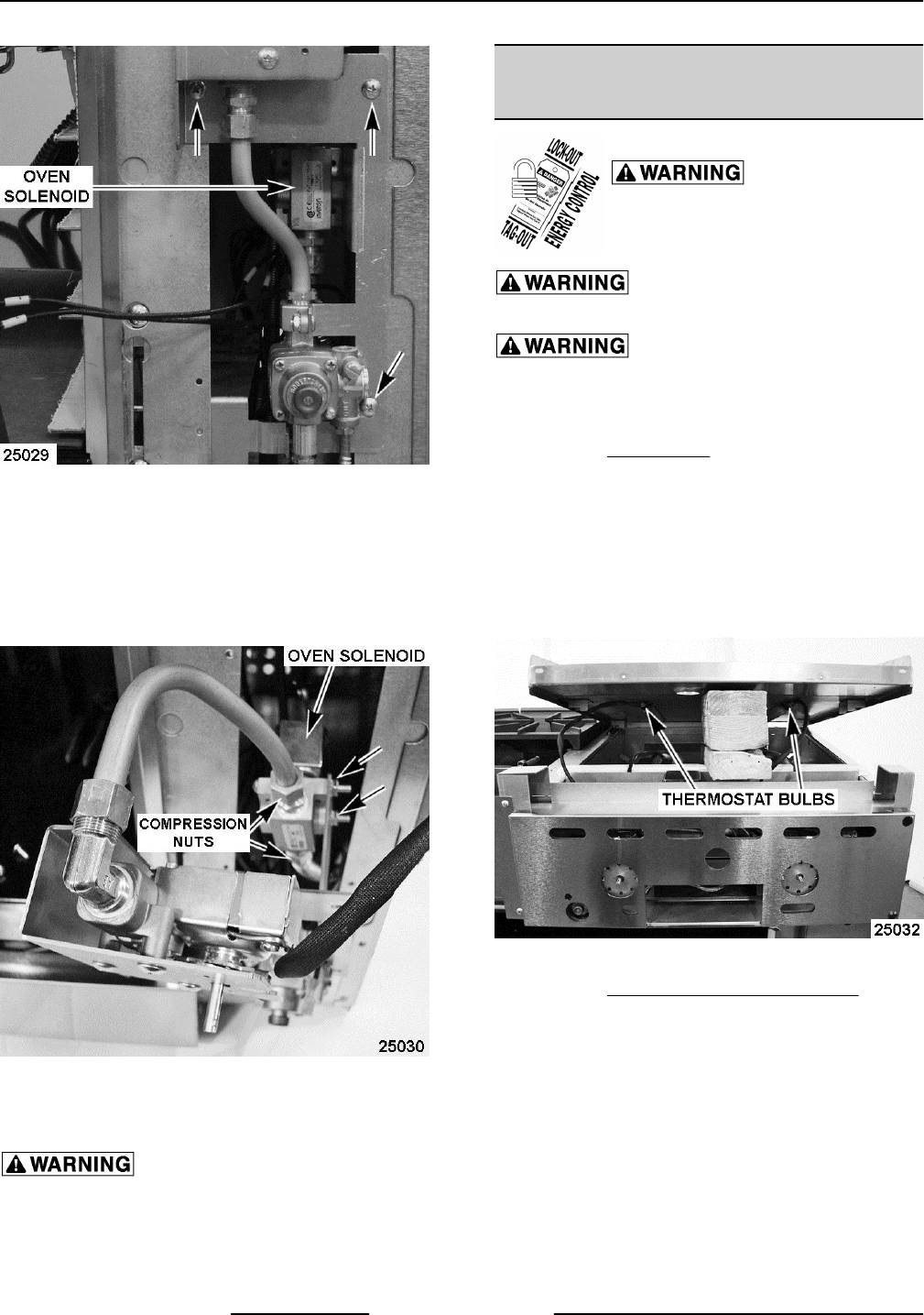
Fig. 39
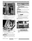
3. Remove compression nuts on the inlet and outlet
of solenoid.
4. Remove screws and mounting nuts securing
solenoid to bracket.
5. Disconnect lead wires from solenoid.
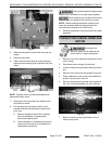
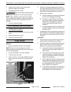
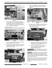
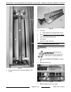
Fig. 40
6. Remove fittings from solenoid for reuse on
replacement valve.
Clean pipe threads and apply thread
sealant that is suitable for use with propane gases.
7. Reverse procedure to install and check for proper
operation.
GRIDDLE THERMOSTAT-COMBO
VALVE
Disconnect the
electrical power to the machine and
follow lockout / tagout procedures.
Shut off the gas before servicing the
unit.
All gas joints disturbed during
servicing must be checked for leaks. Check with a
soap and water solution (bubbles). Do not use an open
flame.
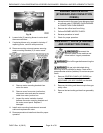
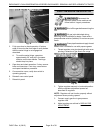
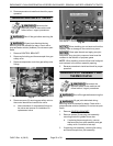
1. Remove BULL NOSE.
2. Raise griddle plate from the front and support
using 4x4 blocks.
3. Pull thermostat bulb out of the holder for the
thermostat-combo valve being replaced.
NOTE: Capillary tube is permanently attached to
thermostat-combo valve.
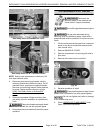
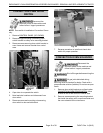
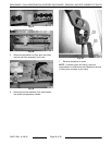
Fig. 41
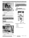
4. Remove CONTROL BRACKET COVER.
5. If installed, remove compression nut on the
flexible tubing gas line that supplies gas to the
manifold on the adjacent open top burner
section.
ENDURANCE / CHALLENGER MODULAR SERIES GAS RANGES - REMOVAL AND REPLACEMENT OF PARTS
F45471 Rev. A (0615) Page 20 of 38