


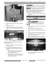
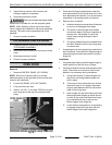
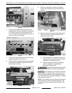
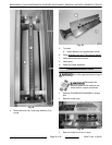
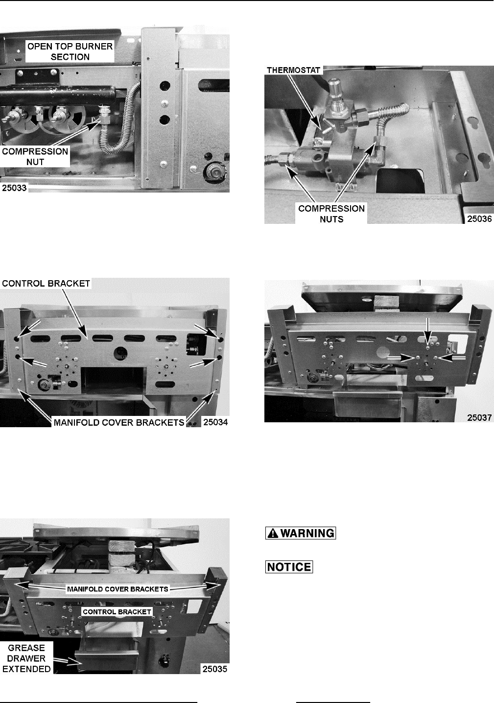
Fig. 42
6. Loosen the recessed screws (4) through the
access holes on the two manifold cover brackets
(L & R) that secure the control bracket to the
oven. The bracket mounting holes are keyed for
removal of the control bracket.
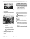
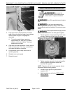
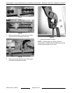
Fig. 43
7. Lift up control bracket and tilt forward to access
griddle thermostat-combo valves.
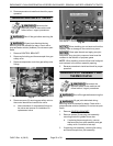
8. Partially install the grease drawer leaving enough
of the drawer extended to support the control
bracket while servicing.
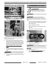
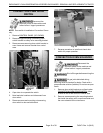
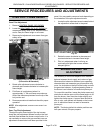
Fig. 44
9. Remove compression nuts from thermostat-
combo valve fittings for the thermostat being
replaced.
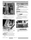
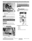
Fig. 45
10. Remove screws (3) securing thermostat-combo
valve to the control bracket and remove the
thermostat-combo valve.
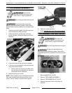
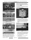
Fig. 46
A. Note orientation of compression fittings on
the thermostat-combo valve and remove for
installation on replacement valve.
B. Remove insulation sleeve from capillary
tube for installation on replacement
thermostat capillary tube.
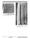
Clean pipe threads and apply thread
sealant that is suitable for use with propane gases.
When installing, do not bend and kink the
capillary tubes or damage to the controls may occur.
Ensure capillary tubes are routed properely through
mounting slots before lowering the griddle or damage
to the controls may occur.
NOTE: When installing, ensure orifice hood is aligned
and centered in the burner assembly opening. The
griddle orifice bracket must be perpendicular to the
manifold.
ENDURANCE / CHALLENGER MODULAR SERIES GAS RANGES - REMOVAL AND REPLACEMENT OF PARTS
Page 21 of 38 F45471 Rev. A (0615)