


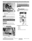

B. While holding outer shaft in place, turn inner
screw using a small flat edge screwdriver
1/8 turn clockwise to decrease and
counterclockwise to increase. 1/4 turn =
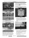
35°F. See picture Fig. 72 under
CONVECTION OVEN THERMOSTAT-
COMBO VALVE ADJUSTMENT.
C. Verify temperature setting at 350°F (or
customers preferred setting). Allow griddle
to cycle 3 times.
NOTE: You must allow the griddle to cycle 3 times to
stabilize oven temperature or the calibration
adjustment may be invalid.
D. Take a temperature reading. If temperature
is within acceptable limits, continue to next
step. If temperature is not within 20°F then
readjust as outlined in this procedure. If 3
consecutive adjustments do not produce
acceptable results, replace thermostat and
verify calibration.
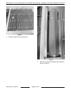
E. Apply a small amount of a non permanent
type sealer (preferably fast drying) such as
nail polish or equivalent around the inner
screw head to prevent movement during
outer shaft rotation. Allow sufficient time for
the applied sealer to dry then install knob.
See TOOLS.
F. If calibrating at 350°F, verify temperature at
400°F. If calibrating at a customer preferred
temperature setting, select one temperature
setting above the customer preferred
setting. If the customers temperature setting
is 450F, then calibrate at that temp only.
Allow oven to cycle 3 times at the
temperature setting. If actual oven
temperature is not within 20°F of the setting,
replace thermostat and verify calibration.
THERMOCOUPLE TEST
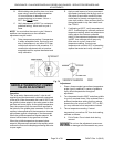
Operation
The thermocouple supplies a DC millivolt signal (MV)
to the gas safety valve when heated by the pilot flame.
The gas safety valve will shut off gas flow to the pilot
and main burner in case of a pilot outage. When
energized by the thermocouple voltage, the gas safety
valve is held open to permit gas flow to the pilot and
provide gas for the burner when the oven thermostat
calls for heat. The pilot flame height is controlled by
an adjustable needle valve located under a small
cover screw on the gas safety valve.
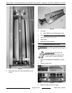
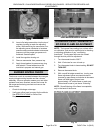
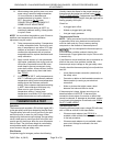
Pilot Checks
If experiencing pilot outages, perform the following:
Visually check pilot flame for the proper contact on
thermocouple and adjust as outlined under OVEN
PILOT FLAME HEIGHT. If adjustment does not result
in a pilot flame of proper height, then gas might not be
flowing properly to the pilot.
Check for:
• A plugged pilot orifice.
• Kinked or plugged pilot gas tubing.
• Low gas supply pressure.
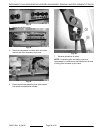
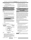
Thermocouple Checks
NOTE: Tubing connection from the thermocouple tip
to gas safety valve is an electrical connection and
must be clean and dry. Do not use any sealing
compound on the threads of thermocouple nut.
Do not overtighten the thermocouple nut
or the insulator could be crushed, shorting the
thermocouple. Finger tighten the nut plus 1/4 turn with
a wrench only.
If pilot flame is correct and there are no excessive air
drafts in the room, then problem is either the
thermocouple output voltage or the gas safety valve.
Visually check the thermocouple tip (hot end) and tube
lead for:
• Loose thermocouple connection (electrical) at
the safety valve.
• Corrosion or debris on the threaded connector or
thermocouple tip causing a poor electrical
connection.
• Kinks or pinches that might cause a short
between the tube and the wire inside.
If thermocouple is loose, tighten mounting nut as
described above in NOTICE. If thermocouple
connection shows signs of corrosion or debris that
cannot be cleaned; or damage as described, replace
it and check pilot operation as outlined under
OVEN
PILOT FLAME HEIGHT.
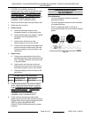
Thermocouple Test
Check the thermocouple output voltage (DC millivolts)
with a VOM as outlined in the steps below.
• If thermocouple adaptor (see TOOLS) is
available, check closed circuit voltage as outlined
in the test procedure.
• If thermocouple adaptor is not available, check
open circuit voltage as outlined in the test
procedure.
ENDURANCE / CHALLENGER MODULAR SERIES GAS RANGES - SERVICE PROCEDURES AND
ADJUSTMENTS
F45471 Rev. A (0615) Page 32 of 38