


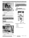

ELECTRICAL OPERATION
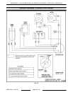
COMPONENT FUNCTION
Power Cord ........... Connects range to power source.
On/Off Switch ......... Provides power for the convection oven motor and solenoid valve.
Solenoid Valve ....... Allows gas flow to the convection oven burner assembly when solenoid is energized by
the door switch (normally closed valve).
Door Switch .......... Removes power from convection motor and solenoid valve when oven door is open (N.O.
- held closed).
Convection Oven
Motor (Single
Phase) ................
Circulates heated air inside the oven. The motor electrical power is routed through door
switch.
Junction Box ......... Connection point for electrical wires.
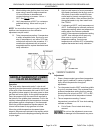
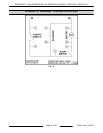
SEQUENCE OF OPERATION -
CONVECTION OVEN
Refer to AI3549 SCHEMATIC DIAGRAM -
CONVECTION OVENS.
Oven temperature is below set point of control.
Convection Oven
1. Conditions.
A. 120VAC to oven controls and is properely
grounded.
B. Power switch off.
C. Door switch held-closed (oven door closed).
D. Pilot lit.
E. Thermostat-combo valve is off.
F. Oven at room temperature.
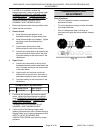
2. Turn power switch on.
A. Solenoid is energized allowing gas flow to
thermostat-combo valve.
B. Power to oven motor (blower circulates air
inside cavity).
3. Set thermostat knob to 350°F.
A. Thermostat-combo valve calls for heat and
opens internal valve to allow gas flow to
burner.
B. Pilot lights the burner and heating begins.
4. Oven reaches setpoint temperature. Thermostat-
combo valve closes internal valve to stop gas
flow to burner.
5. Door switch opened (oven door open).
A. Power is removed from oven motor.
6. Oven door closed. Door switch contacts close
and oven motor resumes operation.
7. Thermostat-combo valve cycles the burner as
required to maintian setpoint temperature untill
thermostat knob is turned to off; or power switch
off.
ENDURANCE / CHALLENGER MODULAR SERIES GAS RANGES - ELECTRICAL OPERATION
F45471 Rev. A (0615) Page 34 of 38